Date
9/7/2018
File
BSR-2114/MAR
Document Number
921211401_09_002
Page
24 από 74
24
The above picture shows how the battery mounting if the is a problem of vibration. In the package of the panel there is the
metal parts and the screws for mounting the batteries.
The metal brackets must be fitted at all times.
3.4.3
Connecting points to the loop
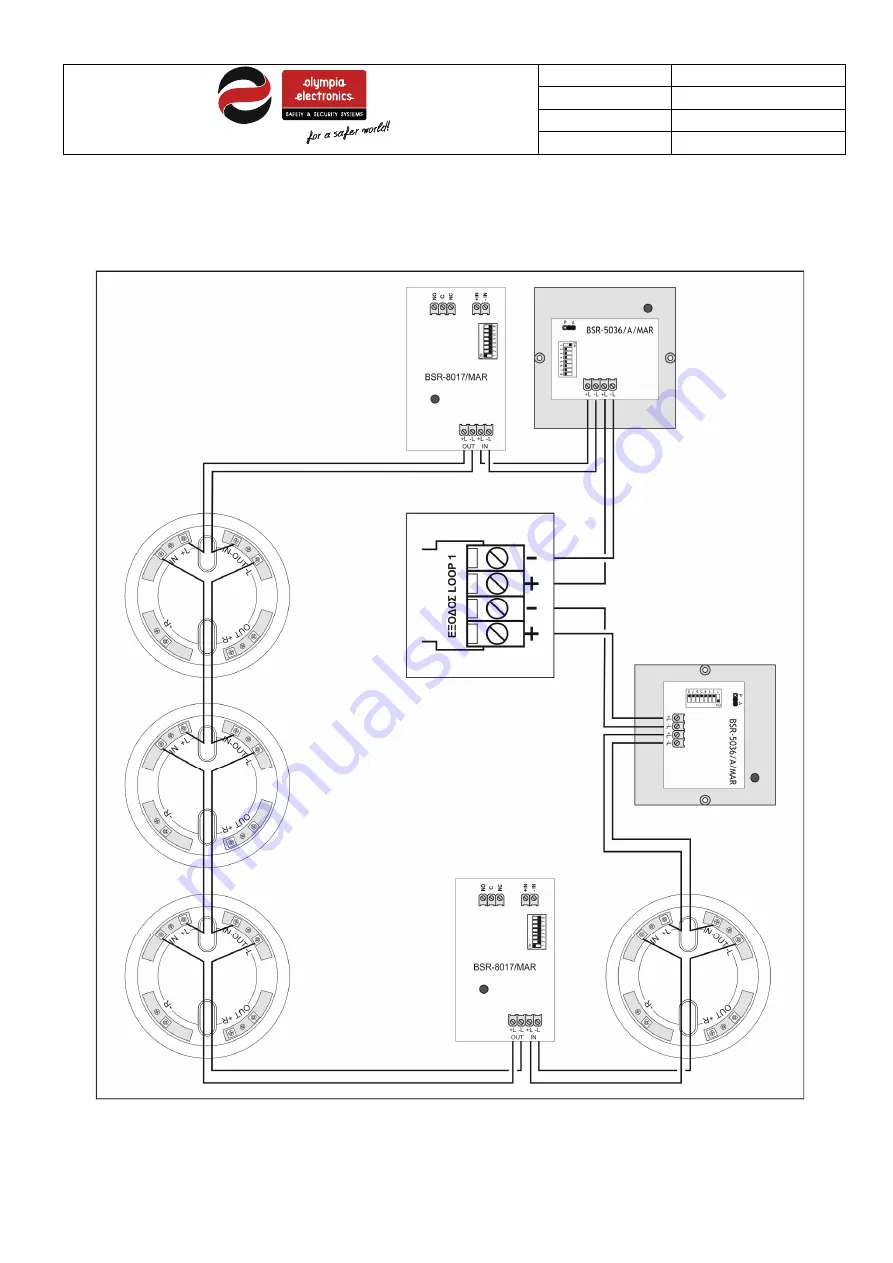
The diagram below show a typical connection between points and the loop.
Figure 3-9
Connecting points to the loop
All compatible with the panel devices ( except sensors ) have 4 terminals for connection to the loop. The terminals are
marked as +L, -L, +L, -L. On one pair +L and –L connect the cables of the loop that come from the panel or the previous


