Date
9/7/2018
File
BSR-2114/MAR
Document Number
921211401_09_002
Page
27 από 74
27
3.4.6
Connection panel with repeaters
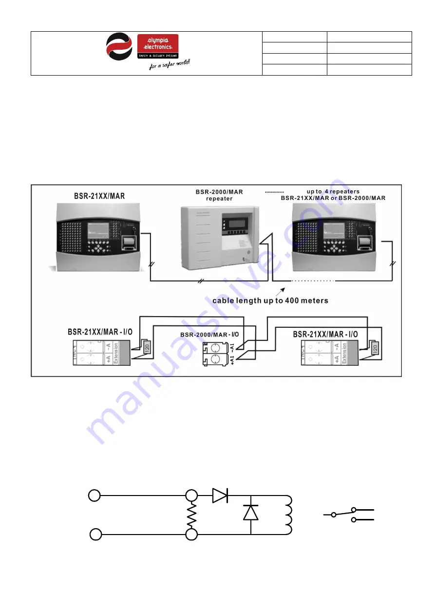
Up to 4 repeater can be connected to a panel. The below figure shows the connection.
The repeaters can be BSR-2000/MAR or BSR-21XX/MAR (in repeater mode).
First of all, the panel must be programmed to work as repeater, and after that they can be connected with panel. After the
wiring the master panel can detect the repeaters from the menu.
Resistances 120Ω must be connected to the terminals of the panel and the last repeaters, as shows at the below figure
The shield of the cables must be connected to the chassis of the panel.
Figure 3-13
Repeaters connection
3.4.7
Fire alarm routing and fire protection connections
The panel has provision of Fire Alarm routing and Fire Protection routing (output type A).
The Fire Alarm Routing terminal is the terminal ,-.
The Fire Protection routing termional is the terminal ,-.
Both outputs are monitored for open and short circuit fault condition by fitting a 5,6KOhm end of line resistor at the receiving
end.
They operate on the voltage-reversing principal so the receiving end equipment must be polarised and suppressed.
A typical connection is shown below
Polarising Diode
Supression Diode
Relay
5,6k terminal
resitance
+
-
Fire Alarm Routing or
Fire Protection Routing
C
NC
NO
Normal
Activation
Figure 3-144
Fire Alarm Routing and Fire Protection connection.


