
921503602_09_009
921503602_09_009
Page 1 from 4
Page 4 from 4
21-28V
1mA
ABS/PC
TECHNICAL CHARACTERISTICS
OPERATION TEMPERATURE RANGE
RELATIVE HUMIDITY
EXTERNAL DIMENSIONS
CONSTRUCTION MATERIALS
TYPICAL WEIGHT
GUARANTEE
OPERATION VOLTAGE
STANDBY CONSUMPTION
ALARM CONSUMPTION
USE
TYPE
DEGREES OF COVER PROTECTION
PRODUCED IN ACCORDANCE WITH
Indoor
Type A
IP 20
1.5mA (with activation LED)
o
-10 to 70 C
Up to 95%
2 years
190gr.
98x94x58mm
EN 54-11
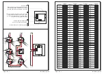
Address
Dipswitch
setting
125
126
127
128
129
130
131
132
133
134
135
136
137
138
139
140
141
142
143
144
145
146
147
148
149
150
1
1
1
1
1
1
1
1
1
1
1
1
1
1
1
1
1
1
1
1
1
1
1
1
1
1
1
1
1
1
ON
ON
ON
ON
ON
ON
ON
ON
ON
ON
ON
ON
ON
ON
ON
ON
ON
ON
ON
ON
ON
ON
ON
ON
ON
ON
ON
ON
ON
ON
2
2
2
2
2
2
2
2
2
2
2
2
2
2
2
2
2
2
2
2
2
2
2
2
2
2
2
2
2
2
3
3
3
3
3
3
3
3
3
3
3
3
3
3
3
3
3
3
3
3
3
3
3
3
3
3
3
3
3
3
4
4
4
4
4
4
4
4
4
4
4
4
4
4
4
4
4
4
4
4
4
4
4
4
4
4
4
4
4
4
5
5
5
5
5
5
5
5
5
5
5
5
5
5
5
5
5
5
5
5
5
5
5
5
5
5
5
5
5
5
6
6
6
6
6
6
6
6
6
6
6
6
6
6
6
6
6
6
6
6
6
6
6
6
6
6
6
6
6
6
7
7
7
7
7
7
7
7
7
7
7
7
7
7
7
7
7
7
7
7
7
7
7
7
7
7
7
7
7
7
8
8
8
8
8
8
8
8
8
8
8
8
8
8
8
8
8
8
8
8
8
8
8
8
8
8
8
8
8
8
121
122
123
124
BSR-5036/A is a addressable manual call point which activates the fire detection panel.
It co-operates with BSR-1116 and BSR-2100 series panels.
It is essential for it to exist in co-operation with the detectors. At least one button has to be
placed in every fire detection system, near to the main control panel.
By pushing the clear plastic cover, the button activates the alarm system. The clear plastic
cover does not brake but can be reset to its original position with the special plastic key
which is included in the package. With this way you can test a specific button as well
maintenance the fire detection panel.
In every fire detection system it is essential that you place one button besides the control
panel and the rest mainly in corridors and exits of the building.
It is mounted in a clearly visible spot, near at exit or ladder and at a height of 1,5 meters.
A red coloured LED that blinks periodically in standby detection mode, is a power
indication LED and indicator for the good operation of the device. When a button issues
an alarm the LED lights. When we silence the sirens the LED remains lit to show us the
detector that issued the alarm.
The LED goes off when we RESET the panel.
Each button has an address with which it is recognized from the panel.
It is forbidden for two devices with same addresses to be connect to the same loop.
The back page contains all the available address settings which are done using the
dipswitch.
The panel references the buttons with the name CALL POINTS
Certification
The addressable manual call point BSR-5036/A is certified from EVPU and
LPCB (1010c/02). Also EVPU controls the production under CPD number:
Description
BSR-5036\A
Addressable
manual call point
1293-CPD-0309 12
EN-54-11: 2001 + A1: 2005
KOLINDROS PIERIAS
60061 GREECE
1293
BSR-5036/A
Addressable manual call point


