background image


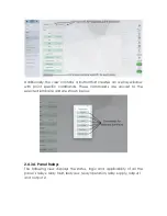
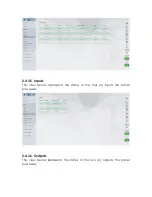
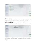
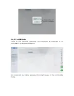
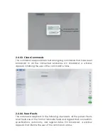
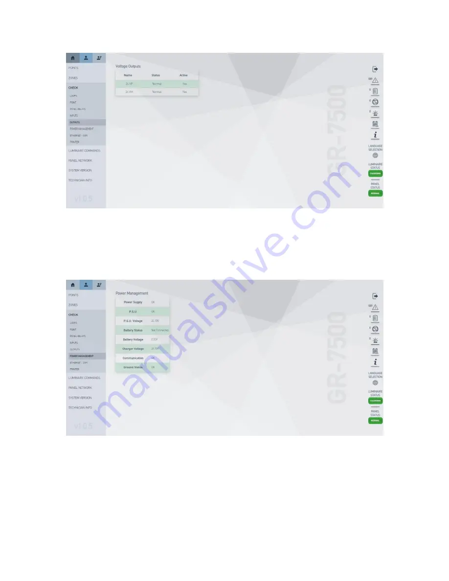
2.4.3.7. Power Management 

This  item  is  responsible  for  the  display  of  core  power  supply  information, 
either  through  the  main  network  or  through  the  panel’s  pre-installed 
batteries,  vital  to  the  unit’s  functionality  in  the  event  of  insufficient  main 
power.  


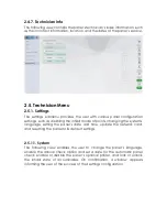
2.4.3.8. Ethernet – WiFi 

This view concerns the user with the panel’s basic connectivity information, 
such as its MAC and IP addresses, subnet mask, default gateway and WPS 
configuration  values  offering  the  option  to  switch  through  the  display  of 
wired or wireless connection information. 

Summary of Contents for GR-7500

Page 1: ...iled presentation and documentation of the web app that accompanies each GR 7500 panel for addressable emergency luminaires It involves the user s flow and navigation throughout the website providing...

Page 2: ...5 2 4 User Menu 6 2 4 1 Points 6 2 4 2 Zones 6 2 4 3 Check 7 2 4 4 Luminaire Commands 12 2 4 5 Panel Network 15 2 4 6 System Version 16 2 4 7 Technician Info 17 2 5 Technician Menu 17 2 5 1 Settings 1...

Page 3: ...that are found within the panel s GUI The web application is unique to each panel and can be accessed using the panel s IP address as the website s URL This user manual is structured using static scr...

Page 4: ...ccessfully logged in Each option contains an array of from top to bottom faults points in test points in inhibit points in emergency events and a table with rudimentary panel information The bottom ri...

Page 5: ...or example the panel s faults and all tables data are arranged with sorting and pagination capabilities This specific table also contains the option to reset the faults within the table for a fresh vi...

Page 6: ...panel The user is given the option to inspect each point for further information through each point s accompanying button 2 4 2 Zones This is a submenu that consists of four 4 different views each one...

Page 7: ...panel 2 4 3 1 Loops This view consists of a simple table with all the necessary information regarding the function of a control loop along with the option to select among the panel s installed loops...

Page 8: ...int specific commands These commands are unicast to the selected luminaire and are shown below 2 4 3 4 Panel Relays The following view displays the status logic and applicability of all the panel s re...

Page 9: ...2 4 3 5 Inputs The view below represents the status of the four 4 inputs the panel possesses 2 4 3 6 Outputs The view below represents the status of the two 2 outputs the panel possesses...

Page 10: ...batteries vital to the unit s functionality in the event of insufficient main power 2 4 3 8 Ethernet WiFi This view concerns the user with the panel s basic connectivity information such as its MAC a...

Page 11: ...regards the status of the panel s on board printer By default the panel does not contain an on board pre installed printer The printer is an additional and separate feature that can be added on the p...

Page 12: ...mmands towards luminaires Each command is broadcast and affects all connected luminaires 2 4 4 1 Function Test This command is broadcast to all luminaires in every zone or only a user selected zone On...

Page 13: ...2 4 4 2 Inhibit Mode Similar to the previous command this command is broadcast to all luminaires in a user selected zone On broadcast a window appears informing the user of the command s status...

Page 14: ...a window appears informing the user of the command s status 2 4 4 4 Reset Faults The command depicted in the following view resets all the panel s faults Most faults are of the form of luminaire fault...

Page 15: ...tempts to re establish connection between each point and the panel On broadcast a window appears that informs the user of the command s status 2 4 5 Panel Network This view contains the basic informat...

Page 16: ...t a panel network because one has not been set 2 4 6 System Version This view holds information regarding the panel s components firmware version the panel s firmware and hardware versions and the con...

Page 17: ...bit mode of points changing the system s language setting the panel s date and time update the network card and resetting the panel to its default settings 2 5 1 1 System The following view enables th...

Page 18: ...t a date and a time for the panel 2 5 1 3 Factory Defaults This view enables the user to restore the panel to its default settings On confirmation a window appears asking the user again for confirmati...

Page 19: ...k card which is the piece of hardware that hosts the panel s web application It becomes available to the user once such an update is available in the network The user is offered the same information r...

Page 20: ...of function and duration tests for the luminaires It also enables the user to stop the already commenced tests at any time 2 5 2 1 Set Function Test The setting of this test includes a weekdays and we...

Page 21: ...on control for each as well as a date and time setting control for each one It is recommended that the two tests be set six 6 months apart from each other to better encapsulate the autonomy of the poi...

Page 22: ...applying the test solely to the panel or the entire panel network as it was set up by the operator including the current panel The duration test checks the battery autonomy of the luminaires and has a...

Page 23: ...d to or situated on the panel This premise pertains to the input output and aux relays to specific point and loop configuration and the deletion of points among others 2 5 3 1 Configure Point This vie...

Page 24: ...ered points and reconfigure them so that only correctly registered points are listed in the appropriate tables On start a progress bar appears to keep track of the process 2 5 3 3 Configure Loops The...

Page 25: ...d mode logic and zone for each of the output relays 2 5 3 5 Inputs This view enables the user to set the preferred mode and zone for each of the input relays The reset option mode does not include the...

Page 26: ...ed and non registered points On this command s selection a window appears asking the user to confirm their action 2 5 4 Panel Network The panel network submenu contains the basic configuration setting...

Page 27: ...ithin the network to activate or deactivate the network and to allow an open ring connection 2 5 4 2 Group Formation The following view allows the user to enable or disable the automatic assignment of...

Page 28: ...r requested operation e Whenever the user tries to send a command that drastically alters the panel s information or settings a pop up window asking for confirmation will appear e g whenever the user...

Page 29: ...action the application will terminate the user s session clear the browser s storage invalidate the authorization token and redirect them to the home screen The user can also terminate their session...

Page 30: ...dynamically updated fully responsive feature accessible from any device that is connected to the same network as the panel It aims at a remote panel access within the same network providing a similar...

Reviews: