background image

Page 3-7

OLYMPIC AUTO-LENGTH

Service

Adjusting the Optical Encoder

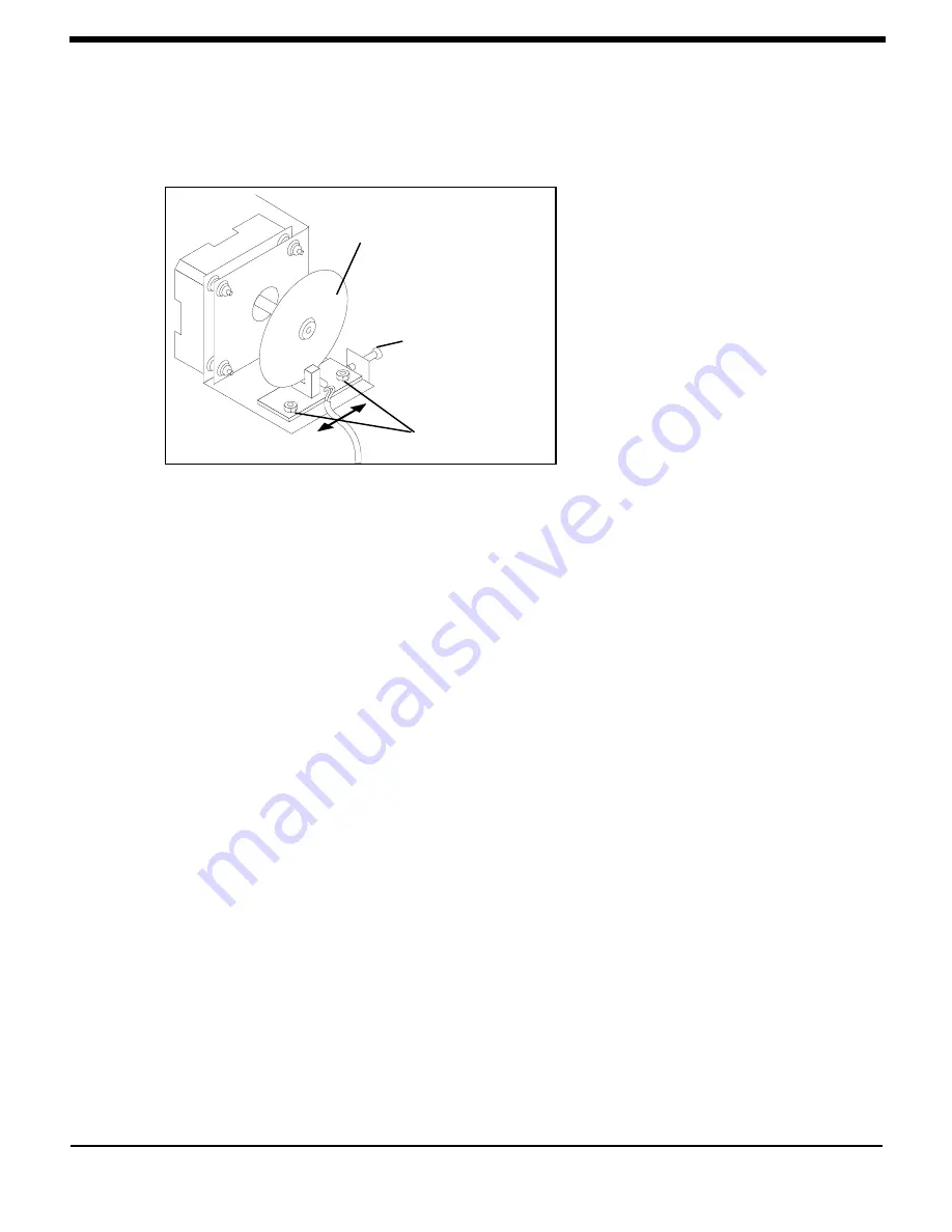
To adjust the optical encoder:

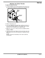
1. Turn the adjusting screw counterclockwise until the sensor can

be moved just to the right of the centerline of the wheel (

Fig. 3

I

).

Optical
Encoder
Wheel

Turn Screw
To Adjust

Loosen
To Adjust

Fig. 3

I

2. Initiate a measuring cycle.

3. If the cycle 

does


not

 complete three readings and return to

home without showing "ERROR" on the display, turn the adjust-
ing screw 1/8 turn clockwise and try again (

Fig. 3

I

).

4. Repeat the 1/8 turn at a time until cycle completes without

showing "ERROR."

5. Tighten the sensor board fasteners, then perform the test cycle

again. Repeat until the cycle completes with tightened sensor
screws.

NOTE:

It should not be necessary to turn screw more than

two full turns.

Summary of Contents for AUTO-LENGTH 20

Page 1: ...1 800 426 0353 in the U S or Canada Instruction Manual OLYMPIC MEDICAL 5900 1st Ave S Seattle WA 98108 USA www olymed com AL 5731A EN N01 CAUTION Read and be familiar with this instruction manual before installing operating or servicing this product 120 Vac ...

Page 2: ...OLYMPICAUTO LENGTH ...

Page 3: ...ng the Tray Length 1 4 Instructions for Cart Mounting 1 6 Calibration 1 8 Canceling Calibration Mode 1 10 Testing for Correct Operation 1 10 Electrical Requirements 1 10 Battery Operation 1 10 Section 2 Operation Caution Summary 2 1 Intended Use 2 1 Measuring the Infant 2 2 The Measurement Cycle 2 3 Controls and Signals 2 4 On Off 2 4 Measure 2 4 Recall 2 4 in cm 2 4 Display 2 5 Cleaning the Auto ...

Page 4: ...he Motor 3 8 Replacing the Motor Pulley 3 9 Replacing the Idler Pulley 3 9 Replacing the Measurement Switch 3 10 Replacing the Home Position Switch 3 11 Replacing the Pivot Assembly 3 12 Measuring Bar Alignment 3 13 Electronic Repairs 3 14 Replacing the Power Supply PCB 3 14 Replacing the Main PCB 3 15 Replacing the Display PCB 3 16 Repair Parts 3 17 Troubleshooting 3 18 Wiring Diagram 3 19 Schema...

Page 5: ...tion Use The Olympic Auto Length is an electronic device for measuring the length of babies Fig 1A Configurations Olympic Medical offers five basic configurations of the Auto Length including tabletop model or cart mounted models and combinations with an Olympic Medical Smart Scale as follows Auto Length catalog no 57310 Auto Length for attachment to a previously purchased Model 20 Smart Scale cat...

Page 6: ...rews 4 Tray Attachment Screw Auto Length Module shown configured for clinic size tray Auto Length BasePlate Auto Length Module shown configured for nursery tray Tray Attachment Screws 4 3 Insert the measuring bar into the pivot assembly Fig 1C 4 Connect the power cord to a hospital grade electrical outlet NOTE When setting up the device for the first time the NiCad battery pack may be fully discha...

Page 7: ... Receptacle PhillipsScrew Fig 1D NOTE The Smart Scale must be calibrated after assembly or chang ing the tray for details refer to the Smart Scale Instruction Manual 3 Insert the measuring bar into the pivot assembly Fig 1C 4 Connect the power cord to a hospital grade outlet NOTE When setting up the device for the first time the NiCad battery pack may be fully discharged and may require charging b...

Page 8: ...y Fig 1C 3 Remove the tray from the Auto Length base or Model 20 scale Fig 1E Tray Leg Receptacle Tray Leg Fastening Screw Auto Length Tray Mount Tray Leg Phillipsscrew SmartScale Tray Mount Fig 1E RearPanel Panel Screws 3 Fig 1F 4 Remove the three screws from the rear panel then lower the panel Fig 1F CAUTION PC boards contain static sensitive parts Always use appropriate ESD protection when the ...

Page 9: ...late Fig 1H 8 Slide the base to its extreme left position as shown in Fig 1I 9 Place and securely fasten the four 8 32 screws in the four alternate holes in the module Fig 1I 10 Place the large cover plate the small plate is not needed and should be stored in a safe place CAUTION To avoid electrical or mechanical damage do not store the small plate inside the enclosure 11 Place the battery pack in...

Page 10: ...ent Tray Leg Fig 1J Auto Length Shown configured for clinic sizetray Base Plate Use 2 short spacerson mounting screws Fig 1L Tray Leg Receptacle Tray Leg Phillips Screw Smart Scale Model 20 Fig 1K Auto Length Shownconfigured for nursery size tray Base Plate Use 2 short spacers on rear mounting screws Remove 2 screws holding Base or Smart Scaletobaseplate Use 2 short spacerson mounting screws Base ...

Page 11: ...te and cart top on front mounting screws Fig 1L Drive the 10 32 screws up through cart top through spacers and into tapped holes in the base plate under the Tray Module Smart Scale 20 Securely tighten the screws 6 Remove the rear panel of the Auto Length Remove the two 8 32 in screws shown in Fig 1M Replace with the 8 32 mount ing screws using the washers from the device Place remaining two short ...

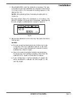
Page 12: ...d RECALL then press MEASURE Release both switches The software version number shows in the upper half of the display Next CALIB shows in the lower half of the display to show that the Auto Length is in its calibration mode Fig 1O 3 All trays have calibration marks Behind the tray you will find a calibration tool held in place by a piece of Velcro Place the calibration tool precisely at the calibra...

Page 13: ...he Auto Length is calibrated and is ready to measure Fig 1Q 5 Remove the calibration tool from the tray then place the Velcro holding pad NOTES The Auto Length automatically turns off after one minute of inactivity The new calibration remains in the Auto Length s memory when the device is turned off it can be recalled when turned on again If an error occurred during the calibration procedure e g t...

Page 14: ...ure ments The measurements should all be within 1 mm 4 If the measurements are not within 1 mm recalibrate the Auto Length and remeasure If the measurements are beyond speci fications see Troubleshooting on page 3 18 ElectricalRequirements CAUTION This device must be connected directly to a hospital grade electrical outlet The Auto Length is rated at 120 Vac 60 Hz 0 4 amperes and must be connected...

Page 15: ...outlet CAUTION To avoid injury do not use this device to transport an infant and never leave the infant unat tended in the tray CAUTION If used on a cart the Auto Length must be securely bolted to the cart using the mounting holes at the bottom of the chassis CAUTION To avoid injury ensure that all four tray legs are secure before placing an infant in the tray Intended Use The Olympic Auto Length ...

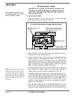
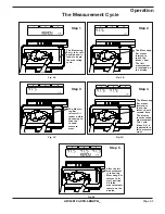
Page 16: ...F Then keeping one hand on the baby press and release MEA SURE Return your hand to the baby and straighten the infant s legs pronating one foot to expose the heel After a two second delay the Auto Length will begin measuring 4 The Measuring Bar will move toward the infant s heel When the Bar contacts the baby s heel the Auto Length sounds an audible beep and records the measurement Fig 2B The Meas...

Page 17: ...orded on the display Fig 2B Step 4 Fig 2D The Measuring Bar moves forward to touch the infant s heel a second time The display records second measurement This cycle steps 3 4 is repeated for a third measure ment Fig 2C Step 3 The Measur ing Bar retracts 2 inches before advancing to take the second measure ment Fig 2E Step 5 After the last measurement is taken the Measuring Bar returns to its start...

Page 18: ...ent has been taken READY appears in the lower half of the display signifying that the Auto Length is ready to take another measurement NOTE The Auto Length automatically turns off after one minute of inactivity Recall Press ON OFF to turn on the device Fig 2G then press RECALL to display the last measurements taken NOTE The Auto Length has a non volatile memory Infor mation shown on the display is...

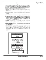
Page 19: ...o Length is in its calibration mode LOW BATTERY Indicates the Auto Length s batteries are de pleted and should be recharged see also Replacing the Battery Pack on page 3 1 Measurements cannot be made while the Low Battery message appears ERROR Appears when the measuring bar jams against an immovable obstacle and the motor stalls BAR JAMMED Appears if the measuring bar is pushed past the rest posit...

Page 20: ...e To clean the Auto Length Wipe all external surfaces using a mild soap and water solution or a liquid disinfectant CAUTION Do not use alcohol to clean tray or mea suring bar as this will damage the plastic The measuring bar lifts up and out of the pivot assembly Wipe measuring bar with a mild soap and water solution or a liquid disinfectant ...

Page 21: ...Battery Pack The internal NiCad batteries can be recharged after full discharge approximately 500 times before requiring replacement Required parts Battery pack 10 8 Vac 1200 mAh catalog no 57394 Screwdriver To replace the battery pack WARNING Electrical shock hazard when enclosure is open Always unplug the power cord from the electrical outlet before cleaning or servicing 1 Remove the three screw...

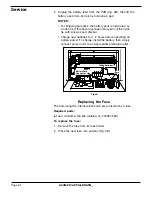
Page 22: ...ssors and discard Charge new batteries for 1 2 hours before operating on battery power To charge install the battery then simply connect power cord to an appropriate electrical outlet NiCadBatteries Fuse Fig 3B BatteryPack Connector Replacing the Fuse The Auto Length s internal electronics are protected by a fuse Required parts Fuse 0 38 amp Slo Blo catalog no 200021 569 To replace the fuse 1 Remo...

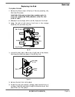
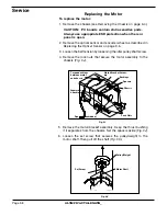
Page 23: ...nt of its travel 3 Grasp the belt at both sides of belt lock on the carriage assembly and pull down Fig 3C Fig 3C UpperCarriage LowerCarriage BeltLock Pull Down Pull Down Fig 3D PulleySlides To Left Loosen Screw Chassis 4 Loosen the idler pulley shaft screw at right side of the chassis then slide the shaft and pulley to the left Fig 3D 5 Remove the belt from both pulleys 6 Thread the new belt betw...

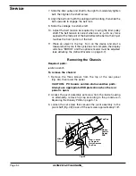
Page 24: ...he cycle does not complete the display will show ERROR and the optical encoder must be adjusted see Adjusting the Optical Encoder on page 3 7 Removing the Chassis Required parts Allen wrench To remove the chassis 1 Remove the three screws from the top of the rear panel Fig 3A then lower the panel CAUTION PC boards contain static sensitive parts Always use appropriate ESD protection when the rear p...

Page 25: ...he tee nut flanges 7 Pull the chassis out of the enclosure It may be necessary to hold the pivot assembly while removing the chassis from the enclo sure 8 To reassemble reverse steps 1 6 NOTE Do not overtighten the tee nuts Ensure that the home position switch wire Fig 3N is routed away from pulley and weight Tee Nuts Optical Encoder RibbonCable Connector Carriage Ribbon Cable Connector Tee Nuts T...

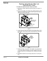
Page 26: ...wn in Fig 3G Motor Optical Encoder Wheel Screws 2 Fig 3G OpticalEncoder CircuitBoard Spacers Set Screw Optical Encoder WheelPulls offShaft Motor Fig 3 8 3 Loosen the set screw that secures the encoder wheel to the motor shaft then pull the encoder wheel straight off of the shaft Fig 3H 4 Replace all faulty components then tighten the optical sensor circuit board fasteners snugly but loose enough t...

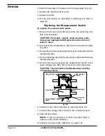
Page 27: ... Fig 3I 2 Initiate a measuring cycle 3 If the cycle does not complete three readings and return to home without showing ERROR on the display turn the adjust ing screw 1 8 turn clockwise and try again Fig 3I 4 Repeat the 1 8 turn at a time until cycle completes without showing ERROR 5 Tighten the sensor board fasteners then perform the test cycle again Repeat until the cycle completes with tightene...

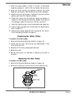
Page 28: ...6 3 Loosen the belt tension by loosening the idler pulley shaft screw 4 Remove the lock nuts that secure the motor assembly to the chassis Fig 3J Fig 3J Grommets Bushings Torquebushings between motor andchassis Spacers onehidden Lock Nuts Chassis Spacers Bushings Motor BracketAssem bly Motor Shaft Pulley Weight SetScrew Fig 3K 5 Remove the motor bracket assembly Keep the thrust bushing if it separ...

Page 29: ... the Optical Sensor and Encoder Wheel see page 3 6 12 Test for proper operation per the instructions in Replacing the Belt on page 3 3 13 Replace the chassis assembly into housing per the instruc tions in Replacing the Belt on page 3 3 Replacing the Motor Pulley To replace the motor pulley 1 Remove the belt see Replacing the Belt on page 3 3 2 Loosen the set screw that secures the pulley weight to...

Page 30: ...ews securing the measurement switch to the upper carriage Fig 3M then remove the switch assembly CAUTION Takecarenottostripthreadswhenremoving or replacing screws UpperCarriage Measurement Switch Screws WireClamp Connector Board LowerCarriage CarriageRibbon Cable Fig 3M 3 Slide the old pulley off replace it with the new pulley Fig 3L 4 Replace the retaining ring Fig 3L 5 Replace the belt 6 Set the...

Page 31: ...pen 2 Remove the screws that secure the switch to the chassis Fig 3N Fig 3N Home Position Switch Pulley Weight Chassis 3 Disconnect the switch assembly wiring at the circuit board connector 4 Install the new switch assembly connecting it to the circuit board 5 Adjust the switch so the carriage activates the switch before contacting the chassis NOTE It may be necessary to bend the switch tang to en...

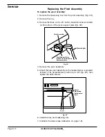
Page 32: ...bottom of the pivot support plate Fig 3O Fig 3P Swivel Measuring BarForward 6 mm 6 mm MeasuringBar Pivot Assembly Fig 3O Pivot Support Plate Allen screws located on bottom of plate 4 Remove the pivot assembly 5 Adjust the new pivot assembly so the measuring bar is swiveled forward of its perpendicular position by 6 mm Fig 3P then tighten the Allen screws 6 Install the tray and measuring bar 7 Cali...

Page 33: ...three 4 40 x 25 button head Allen screws located on the bottom of the pivot support plate Fig 3O 4 Adjust the pivot assembly so the measuring bar is swiveled forward of its perpendicular position by 6 mm Fig 3P then tighten the Allen screws 5 Install the tray and measuring bar 6 Calibrate the device see Calibration on page 1 8 ...

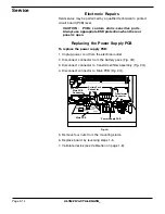
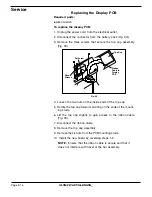
Page 34: ...Power Supply PCB To replace the power supply PCB 1 Unplug power cord from the electrical outlet 2 Disconnect connector from the battery pack Fig 3Q 3 Disconnect connector to transformer filter assembly Fig 3Q 4 Disconnect connector to Main PCB Fig 3Q Fig 3Q BatteryPack Connector Transformer Connector Main PCB Connector Power Supply PCB Main PCB 5 Remove four nuts from the mounting studs 6 Replace ...

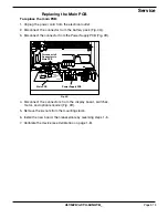
Page 35: ...ig 3Q 3 Disconnect the connector from the Power Supply PCB Fig 3R Fig 3R Main PCB Disconnectall Connectors to Main PCB Power Supply PCB 4 Disconnect the connectors from the display board switches motor and optical encoder Fig 3R 5 Remove the six nuts from the mounting studs 6 Install the new board then reassemble by reversing steps 1 5 7 Calibrate the device see Calibration on page 1 8 ...

Page 36: ... screws that secure the top cap assembly Fig 3S 4 Loosen the two nuts on the inside ends of the top cap 5 Rotate the top cap forward pivoting on the ends of the mount ing studs 6 Lift the top cap slightly to gain access to the ribbon cable Fig 3S 7 Disconnect the ribbon cable 8 Remove the top cap assembly 9 Remove the six nuts from the PCB mounting studs 10 Install the new board by reversing steps...

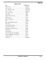
Page 37: ... Display PCB with Display 400678 Measuring Bar 400704 Bar Pivot Assembly 400705 Belt 100346 01 Motor Pulley Weight Assembly 400707 Idler Pulley 400708 Motor Bracket Assembly 400710 Home Switch Assembly 400712 Measurement Switch Assembly 400698 Sensor PCB 400697 Encoder Wheel 400709 Upper Carriage Block with Bearings 400701 Lower Carriage Block with Bearings 400702 Carriage Shaft s 301336 Transform...

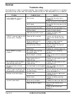
Page 38: ...n Adjust or replace the drive belt see page 3 3 Motor failure Replace the motor see page 3 8 BAR JAMMED message Bar is being prevented from Ensure that bar is not being displays returning to neutral pushed Bar mechanism is jammed Check the bar motion and adjust as needed Measurement switch is Replace the measurement switch malfunctioning see page 3 10 Bar continues to move forward Measurement swit...

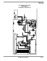
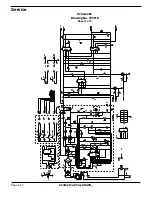
Page 39: ...Page 3 19 OLYMPIC AUTO LENGTH Service Auto Length 120 Vac 60 Hz WiringDiagram Drawing No 700215 Rev B ...

Page 40: ...Page 3 20 OLYMPIC AUTO LENGTH Service Schematic Drawing No 700216 Sheet 1 of 2 ...

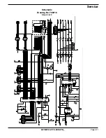
Page 41: ...Page 3 21 OLYMPIC AUTO LENGTH Service Schematic Drawing No 700216 Sheet 2 of 2 ...

Reviews: