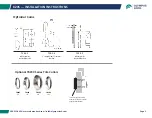
820S — INSTALLATION INSTRUCTIONS/CAM ASSEMBLY
800-525-0954 | www.olympuslock.com | info@olympuslock.com
Page 3
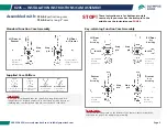
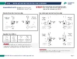
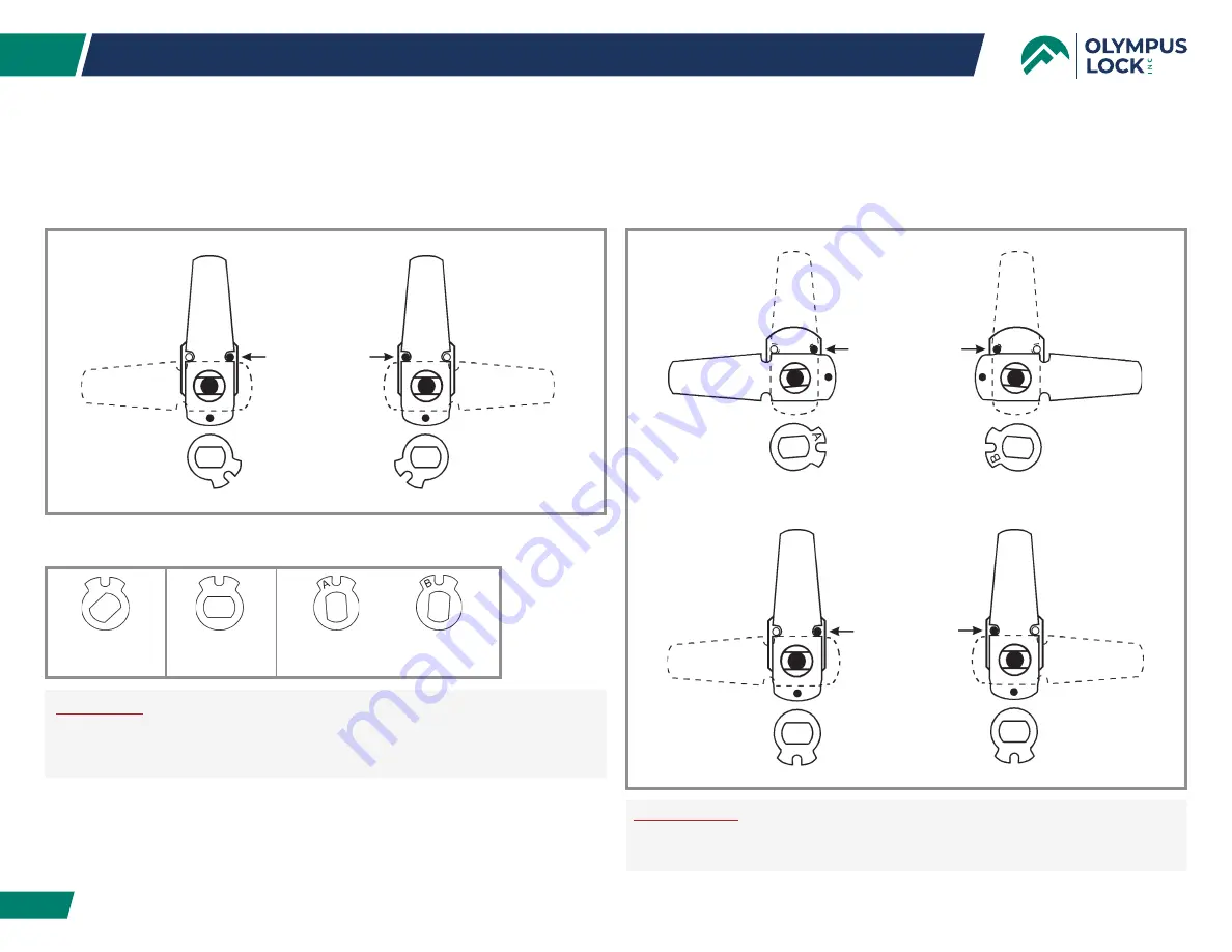
Assembled with:
Special note:
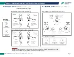
If your cam has a brass pin on the bottom of the cam use these instructions,
otherwise see page 5 for mid-pin cam assembly.
720-CDLM
lost motion cam shifter
(non-key-retaining)
720-CDDM (A Side)
key retaining door
cam shifter
720-KR
key retaining drawer
cam shifter
720-CDDM (B Side)
key retaining door
cam shifter
1
2
3
3
Stop
pin
Stop
pin
LH Door or
Drawer
RH Door
or Drawer
Key removable
in locked or
unlocked position.
Key removable in
locked or unlocked
position.
1
1
L
O
C
K
E
D
L
O
C
K
E
D
2
2
Stop
pin
Stop
pin
Drawer
Key
Retaining
Key removable
in locked
position only.
Drawer
Key
Retaining
Key removable
in locked
position only.
L
O
C
K
E
D
L
O
C
K
E
D
Stop
pin
Stop
pin
LH Door
Key
Retaining
Key removable
in locked
position only.
RH Door
Key
Retaining
Key removable
in locked
position only.
3
3
LOCKED
LOCKED
Standard Function Cam Assembly
Key-retaining Function Cam Assembly
Supplied Cam Shifters
Important:
It is highly recommended that you install the prong driver and lock
cylinder into the lock body and cycle to the locked position before as-
sembling cam, cam shifter and stop pin onto the back of the lock.
720-3-2
vertical long cam
720-3-4
extra long 3” cam
STOP!
These instructions are for bottom-pin style
cams only. If your cam has the brass pin in the
middle, see the instructions on
PAGE 4
.


