background image


Teardown, Cleaning, and Reassembly of the Miscellaneous Parts of the Olympus BH-2 Microscope Frames 

Revision 1 

Page 43 of 45 

If this is the case, it means that the field diaphragm was 
not  at  its  maximally  open  position  when  the  knurled 
field-adjustment  ring  was  reinstalled.    If  this  happens, 
remove  the  filter  holder  and  knurled  ring,  and  then 
reinstall  them  to  obtain  a  different  mesh  point  of  the 
geared  portion  of  the  knurled  ring  with  the  field 
diaphragm assembly, such that the full range of motion 
can be obtained (see 

Figure 188

 an

Figure 189

).  It may 

take a few attempts to find the correct mesh point. 
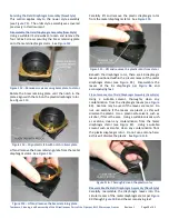
Once  the  full  adjustment  range  of  the  field  diaphragm 
has  been  verified,  use  a  suitable  JIS  screwdriver  to 
reinstall  the  three  m2x7  screws  to  secure  the  filter 
holder in place (see 

Figure 190

). 


Figure 190 

 Secure filter holder in recess of knurled ring 

The  Light  Exit  Assembly  is now  reassembled  and  ready 
to be put back into service. 


Figure 191 

 Light Exit Assembly ready for service 

Collimating the Integral Substage Lighting 

If during the course of servicing the stand, the Light Exit 
Assembly  and/or  the  pillar  arm  have  been  separated 
from  the  base  casting,  it  is  recommended  that  you 
perform  a  collimation  of  the  substage  lighting  system, 
per  the 

Collimating  the  Substage  Lighting  of  the 

Olympus 

BHS/BHSU/BHT/BHTU 

Microscopes


document  in  this  series,  before  using  the  microscope.  

Although  this  collimation  is  not  strictly  required

1

,  it 

should  be  done  if  you  wish  to  obtain  the  best  optical 
performance  that  your  microscope  is  capable  of 
providing. 

A Few Words About Dust Protection 

The  bases  of  the  BHS/BHSU  and  the  BHT/BHTU  stands 
are reasonably well sealed against dust intrusion during 
normal  operation  when  the  lamphouses  are  installed.  
There  are,  however,  a  few  things  to  be  aware  of  for 
long-term  storage  of  these  stands.    On  the  BHT/BHTU 
stands,  the  barrel  of  the  Light  Inlet  Assembly  seals the 
light-inlet port on the back of the base, whether or not 
the 20W lamphouse is installed, so long-term storage of 
BHT/BHTU scopes should not be a problem.   
The rear opening of the BHS/BHSU scopes is a different 
story, however.  The light-inlet  port on these  scopes is 
only  sealed  when  the  100W  lamphouse  is  attached  to 
the stand, since the light-inlet optics are integral to the 
lamphouse  and  are  not  present  in  the  stand.  
Accordingly,  if  the  BHS/BHSU  stand  is  stored  without 
the lamphouse attached, the light-inlet port on the back 
of the base will be wide open, allowing dust to foul the 
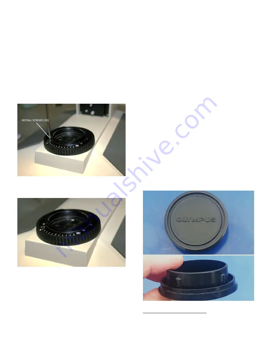
primary surface mirror.  Olympus provided a plastic dust 
cap  (se

Figure  192

  and 

Figure  193

)  to  seal  the  light 

port  when  the  lamphouse  is  not  installed,  and  this 
should be used to keep dust out of the base whenever 
the stand is stored without the lamphouse attached.   


Figure 192 

 Dust cap for BHS/BHSU light port (top view) 


1

 A great many of the BH-2 scopes in use today have been disassembled for 

service  at  one  time  or  another  and  have  not  been  re-collimated  upon 
completion of the repair. 

Summary of Contents for BH2 Series

Page 1: ...mail com Permission is hereby granted to distribute this PDF document in its entirety for personal non commercial purposes only provided that the contents are not modified in any way including the cop...

Page 2: ...Clean Threads for the Locking Thumbscrew BHS BHT ____________________________________________ 18 Servicing the Old Style Slide Mount BHS BHT ___________________________________________________ 18 Cle...

Page 3: ...d Tools Referenced in this Document ___________________________________________ 45 Parts Supplies and Tools____________________________________________________________________ 45 Sources for Parts Sup...

Page 4: ...the locking thumbscrew 18 Figure 55 Clean threads of locking thumbscrew old style 18 Figure 56 Thoroughly clean slide mount base old style 19 Figure 57 Slide mount parts ready for use old style 19 Fi...

Page 5: ...nstall screws to secure the retaining plate 28 Figure 108 Reinstall plastic gear collar onto the rotor 28 Figure 109 Secure the gear collar with two screws 28 Figure 110 Reinstall the slotted stop pin...

Page 6: ...ed retaining ring 37 Figure 161 Unscrew and remove threaded retaining ring 38 Figure 162 Lift and remove the glass field exit lens 38 Figure 163 Blow loose dust from the glass lens 38 Figure 164 Clean...

Page 7: ...us BH 2 Microscope Frames Revision 1 Page 7 of 45 Figure 190 Secure filter holder in recess of knurled ring 43 Figure 191 Light Exit Assembly ready for service 43 Figure 192 Dust cap for BHS BHSU ligh...

Page 8: ...set slotted Lens Handling Suction Tool item 9 of Appendix 1 Lens Spanner Tool bent tips item 8 of Appendix 1 A Few Words about JIS Screws Screws with JIS heads are found in much of the older equipment...

Page 9: ...used on the BHSU BHTU stands The BHS BHT locking thumbscrew includes a spring loaded plunger and consists of six separate parts This locking screw can be identified by the presence of the slotted end...

Page 10: ...Figure 7 Mounting disk from an old binocular head Carefully place the circular dovetail of the mounting disk see Figure 7 into the dovetail recess for the viewing head using the circular dovetail to d...

Page 11: ...e in the end of the plunger shaft see Figure 12 Figure 12 Carefully remove e clip from the plunger shaft Remove the clamp holding the mounting disk in place and remove the mounting disk from the dovet...

Page 12: ...nt acetone to remove any grease or other contaminants from the bore of the stationary inner barrel of the locking thumbscrew see Figure 18 Figure 18 Clean the bore of the stationary inner barrel Use a...

Page 13: ...igure 24 Figure 24 Insert plunger into bore of the inner barrel Apply a light coating of a suitable grease item 1 of Appendix 1 to the exposed threads of the stationary inner barrel of the locking thu...

Page 14: ...t end Use a suitable clamp with non marring jaws to hold the mounting disk in the slid over position to keep the end of the plunger shaft exposed see Figure 30 Figure 30 Clamp mounting disk to keep sh...

Page 15: ...locking thumbscrew the locking thumbscrew must be removed from the pillar arm so that any thick or hardened grease or contaminants can be removed from the threads and then reinstalled into the pillar...

Page 16: ...nd a suitable solvent acetone to clean any grease or contaminants from the threads of the tapped hole in the pillar arm see Figure 41 Figure 41 Clean the threads of the tapped hole Reinstall the Locki...

Page 17: ...w ready to provide many more years of trouble free service see Figure 35 Figure 47 Refurbished thumbscrew is ready for use Nosepiece Slide Mount There were two versions of nosepiece slide mounts used...

Page 18: ...Figure 53 Figure 53 Remove the slide mount from the pillar arm Clean Threads for the Locking Thumbscrew BHS BHT Using a pipe cleaner and a suitable solvent e g acetone clean the inner threads of the t...

Page 19: ...le slotted screwdriver loosen and remove the stop screw for the nosepiece slide mount locking block see Figure 58 Figure 58 Remove the locking block stop screw Using a suitable slotted screwdriver loo...

Page 20: ...unt base making sure the bearing surface of the locking block is in contact with the mount base see Figure 64 Figure 64 Position locking block under slide mount base Align the pivot screw hole in the...

Page 21: ...Using a suitable JIS screwdriver reinstall the three m2 6x5 screws to secure the nosepiece slide mount to the BHS BHT pillar arm see Figure 70 Figure 70 Secure nosepiece slide mount with screws Reinst...

Page 22: ...sembly from the base casting see Figure 77 being very careful so as to not damage the Light Exit Assembly with the field diaphragm assembly the two assemblies are very close in proximity and the refle...

Page 23: ...ar from the diaphragm rotor if it will come loose See Figure 81 Figure 81 Lift and remove the plastic gear collar Using a suitable JIS screwdriver loosen and remove the four m2 6x5 screws securing the...

Page 24: ...to clean them If the leaves are plastic do not use acetone but instead use a plastic safe solvent such as alcohol Figure 88 Thoroughly clean the diaphragm leaves Using a suitable solvent thoroughly c...

Page 25: ...he pivot pin on the end with the relief notch see Figure 90 if applicable into one of the pivot holes in the metal diaphragm stator See Figure 92 Figure 92 Reinstall first diaphragm leaf into the stat...

Page 26: ...ighth leaf the end with the relief notch if applicable under the lifted ends of the existing leaves and place the pivot pin into the appropriate hole beneath the lifted leaves Use the pencil markings...

Page 27: ...e metal diaphragm stator The two orthogonally located holes for the screws should be in the position shown in Figure 105 Figure 105 Orientation of the screw holes in the rotor If the two orthogonal sc...

Page 28: ...tor Using a suitable JIS screwdriver reinstall the two m2 6x5 screws to secure the plastic gear collar in place on the diaphragm rotor See Figure 109 Figure 109 Secure the gear collar with two screws...

Page 29: ...tator See Figure 115 Figure 115 Lift and remove the plastic rotor from stator Beneath the diaphragm rotor there are 10 diaphragm leaves positioned within the circular recess of the metal diaphragm sta...

Page 30: ...ate with the four tapped holes in the stator See Figure 118 Figure 118 Reinstall brass retaining plate onto stator Using a suitable JIS screwdriver reinstall the four m2 6x5 screws to secure the brass...

Page 31: ...nlet Assembly BHT BHTU Using a 1 3mm or 050 hex tool loosen and remove the two m2 6x3 setscrews securing the Light Inlet Assembly into the bore of the base casting see Figure 125 Figure 125 Remove set...

Page 32: ...and remove adiabatic glass disk Remove the upper spacer tube from within the metal barrel see Figure 130 Figure 130 Remove the upper spacer tube Use a suitable lens suction tool item 9 of Appendix 1 t...

Page 33: ...the lower retaining ring Use a suitable lens suction tool item 9 of Appendix 1 to carefully lift and remove the lower frosted glass disk from within the metal barrel see Figure 137 Figure 137 Careful...

Page 34: ...onto the lower retaining ring within the metal barrel see Figure 141 Figure 141 Place collector lens into metal barrel Carefully place the lower spacer tube into the metal barrel and press it down un...

Page 35: ...aining ring to the glass disk The Light Inlet Assembly is now ready to be reinstalled into the microscope stand see Figure 148 Figure 148 Ready to reinstall the Light Inlet Assembly Reinstall Light In...

Page 36: ...ons are shown in top view in Figure 153 and in bottom view in Figure 154 with the plastic metal version on the left and the all plastic version on the right in both figures Figure 153 Top view of the...

Page 37: ...he filter holder in place in the recess of the knurled field adjustment ring see Figure 156 Figure 156 Remove screws securing the filter holder Lift and remove the filter holder from the recess in the...

Page 38: ...f Appendix 1 to remove as much loose dust and debris as possible from the glass field exit lens see Figure 163 Figure 163 Blow loose dust from the glass lens Use a suitable lens cleaning solution and...

Page 39: ...ws securing the frame of the Light Exit Assembly to the base casting of the stand see Figure 168 Figure 168 Remove screws securing frame to the base Carefully lift and remove the frame of the Light Ex...

Page 40: ...ush item 10 of Appendix 1 to carefully clean the wetted reflective surface of the mirror by gently wiping the surface with the soft bristled brush see Figure 175 Figure 175 Carefully clean the primary...

Page 41: ...n the base casting making sure you do not touch or damage the fragile primary surface mirror see Figure 180 Figure 180 Re install Light Exit frame into base cutout Align the three holes in the Light E...

Page 42: ...oil to the plastic filter holder Place the filter holder into the center recess of the knurled field adjustment ring see Figure 186 Figure 186 Place the filter holder into recess of field ring Rotate...

Page 43: ...Although this collimation is not strictly required1 it should be done if you wish to obtain the best optical performance that your microscope is capable of providing A Few Words About Dust Protection...

Page 44: ...available for download at various microscope related hobbyist sites on the internet These can be found by searching for the titles in an internet search engine such as Google Olympus Research Microsco...

Page 45: ...3 Super Lube Synthetic Oli w PTFE 4oz Super Lube 51004 Amazon 10 99 4 Sparkle Lens Cleaning Solution CLS Amazon 18 43 5 Lens cleaning Tissue 50 sheets Tiffen Amazon 8 95 Table 1 Supplies for servicing...

Reviews: