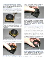
Teardown, Cleaning, and Reassembly of the Miscellaneous Parts of the Olympus BH-2 Microscope Frames
Revision 1
Page 27 of 45
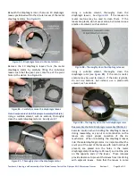
Figure 101
–
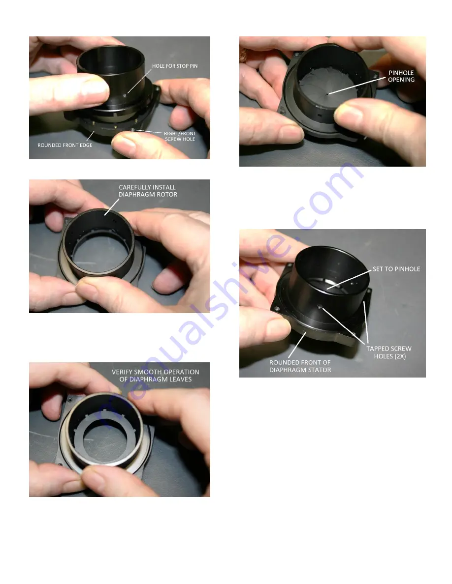
Proper orientation of field diaphragm rotor
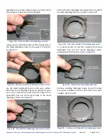
Figure 102
–
Carefully reinstall the field diaphragm rotor
Carefully rotate the diaphragm rotor, making sure the
leaves move smoothly without interference or binding.
See
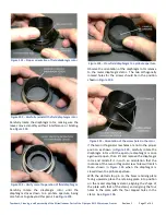
Figure 103
–
Verify smooth operation of field diaphragm
Carefully rotate the diaphragm rotor until the
diaphragm closes down to a pinhole aperture, being
careful not to go beyond this point. See
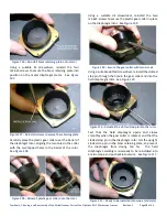
Figure 104
–
Close field diaphragm to a pinhole aperture
Observe the orientation of the diaphragm rotor relative
to the metal diaphragm stator. The two orthogonally
located holes for the screws should be in the position
shown in
Figure 105
–
Orientation of the screw holes in the rotor
If the two orthogonal screw holes are not in the proper
position as shown in
, carefully rotate the
diaphragm rotor until the aperture diaphragm is once
again wide open, then lift and remove the diaphragm
rotor and reinstall it in such an orientation that the
locations of the two orthogonal screw holes will match
those shown in
closed down to a pinhole aperture.
With the slotted stop pin on the brass retaining plate
facing upwards, place the retaining plate into position
on the metal diaphragm stator, aligning the shape of
the plate with that of the stator, and aligning the four
holes in the plate with the four tapped holes in the
stator. See


