Page 1: ...OLYMPUS POLARIZING MICROSCOPE INSTRUCTION MANUAL I MODELBHSP...
Page 2: ...e coarse adjustment Do not twist the two coarse adjustment knobs in the opposite directions simultane ously which might cause damage 4 Ascertain that the line voltage selector switch on the base plate...
Page 3: ...g on the Light Source Adjusting the Observation Tube Use of the Orientation Plate 11 Centering the Condenser 12 Centering the Stage 13 Centering the Objectives Use of Iris Diaphragms Focus Adjustment...
Page 4: ...circular stage with stage plate centering wrenches BH2 SRP paired and stage clips paired BHS 751P 1 1 1 1 1 1 1 1 1 2 1 1 1 1 1 1 1 1 1 1 Test plates 753P 1 1 1 1 1 1 1 1 1 2 1 1 1 1 1 1 1 1 1 1 Quar...
Page 5: ...11 NOMENCLATURE The Model BHSP consists of various components a s shown in the photo below Revolving nosepiece Objective Stage Condenser Base Observation tube...
Page 6: ...Take care t o keep all glass surfaces clean and avoid scratching the glass surfaces NOTE For numbers 0 0 0 and 0 please refer t o explanations i n detail o n the next page Quarter wave plate Sensitive...
Page 7: ...he mounting dove tail afrom above slowly Fig 2 3 Lower the stage until it comes in contact with the stop pin 0 then clamp with screw Fig 2 0 Mounting the revolving nosepiece Fig 1 Fig 2 1 Loosen the n...
Page 8: ...ight path selector knob The knob can be operated in 3 positions to deflect the light as desired Field iris diaphragm ring Arrow mark t 0 indi For continuously variable light Accepts the filter holder...
Page 9: ...lever Stage centerinq knob Pre focusinglever adjustment knob Swing out knob for top lens Y Condenser N A is 0 9 when top lens swings out N A is 0 25 removal of the Bertrand lens from the light path B...
Page 10: ...cuit breaker protrudes its central part to cut off the electrical power in case of the dimmer circuit trouble due to short circuit etc or overcurrent To restore the breaker press the central part If t...
Page 11: ...ing in the desired objective L Set the condenser analyzer and Bertrand lens correctly according to your microscopic 2 purpose pages 15 and 16 M Fine focus 0 N Adjust aperture iris diaphragm and field...
Page 12: ...usting the Observation Tube 1 A t the time of inserting the eyepieces into the observation tube take care to insert the eyepiece with cross hairs or micrometer of your choice into the right eyepiece t...
Page 13: ...e adjusted for optimum extinc tion by means of the orientation plate provided in the following steps 1 Bring the 10X objective into the light path and make sure that the red dots aon both intermediate...
Page 14: ...en slide is too thick it is sometimes impossible to obtain a sharply focused Image 5 While widening the diameter of the field progressively use the condenser centering screws to bring the diaphragm im...
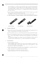
Page 15: ...Diag c Ir Repeat this procedure until the stage centra tion is complete After completing the cen tration remove the wrenches Fig 13 Diag a Diag b Diag c F Centerins the Obiectives This objective centr...
Page 16: ...coarse focus has been accomplished This prevents further upward travel of the stage by means of the coarse adjustment knobs and automatically H Focus Adjustment 1 Tension of Coarse Adjustment Knobs an...
Page 17: ...these bubbles greatly deteriorate the lens performance a After use carefully wipe off the immersion oil deposited on the lens surfaces with gauze moistened with xylene Never leave oil on the lens sur...
Page 18: ...lluminate the specimen with no need to immerse between the condenser and specimen slide 2 Bring the specimen into focus rotate the Bertrand lens turret ring into the IN position 3 Focus on the interfe...
Page 19: ...0 52 400X 3 0 0 N A Numerical aperture The numerical aperture represents a performance number which could be compared t o the relative aperture f number of a camera lens N A values can be used for di...
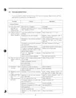
Page 20: ...ay Swing it out of light path Re insert condenser all the way Push plate all the way until it clicks Open diaphragm fully d Excessive image contrast c Dust or dirt is visible in field of e Resolution...
Page 21: ...nser is not correctly centered Condenser is lowered excessively j Crossed filter position is not attained Center condenser Raise condenser Condenser top lens is not in light path 2 Electric System b O...
Page 22: ...men is mounted on stage up side down Reverse specimen 4 Observation Tube a Incomplete binocular vision lnterpupillary distance is not cor rectly adjusted Diopter adjustment is incomplete User is unacc...