background image

19

BX43


3

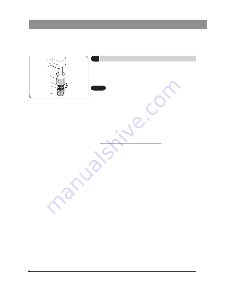
  Adjusting the X- and Y-Axis Knob Tension  

(Fig. 27)

1. Hold the X-axis knob @ and slide up the Y-axis knob 

2

 up to expose 

the adjustment knobs.

2. Turning  the  X-axis  adjustment  knob 

3

  or  Y-axis  adjustment  knob  | 

clockwise  (in  the  direction  of  the  arrow)  increases  the  tension  and 
counterclockwise decreases it.

  If the tension is adjusted to tight, a creaking sound may be heard 

during stage travel, and the stage stopping accuracy may be 
imperiled.

} After long hours of use, the stage guide may be deviated and the stage 

travel range may be decreased.

  However, this is not malfunction and can be corrected easily as described 

below.

[Treatment]

Horizontal direction:  Hold the specimen holder and move the stage guide 

to the left and right so that it hits the stoppers.

Vertical direction: 

Hold the upper stage and move it to the front and rear 
so that it hits the stoppers.

  Stage Feed Knob Rubber Caps (Optional)

} When the X- and Y-axis knobs are fitted with the rubber caps, the knobs 

can  be  adjusted  without  slipping  and  fine  adjustment  is  possible  by 
holding the knobs with a very light force. The knob rubber caps also 
reduce fatigue after long hours of operation.

  The U-SHGT thick type (thickness 5 mm) and U-SHG thin type (thickness 

2 mm) knob rubbers are available.

  To attach the knob rubbers:

  First fit the larger knob rubber to the Y-axis (upper) knob from below it, 

then fit the smaller knob rubber to the X-axis (lower) knob from below it.

Fig. 27

1

3

4

2

CAUTION

Summary of Contents for BX43

Page 1: ...o ensure the safety obtain optimum performance and to familiarize yourself fully with the use of this microscope we recommend that you study this manual thoroughly before operating the microscope Reta...

Page 2: ...limits are designed to provide reasonable protection against harmful interference when the equipment is operated in a commercial environment This equipment generates uses and can radiate radio freque...

Page 3: ...usting the Contrast 12 5 USING THE CONTROLS 5 1 Base 13 15 1 Adjusting the Brightness 13 2 Setting the LIM Brightness 13 3 Using the Filters Halogen Bulb Operation Only 14 5 2 Focusing Block 16 17 1 F...

Page 4: ...PROPER SELECTION OF THE POWER SUPPLY CORD 39 40 7 TROUBLESHOOTING GUIDE 8 SPECIFICATIONS 9 OPTICAL CHARACTERISTICS UIS2 Series 10 ASSEMBLY See this section for the replacement of the light bulb 11 HAL...

Page 5: ...e warranted 5 Always ensure that the grounding terminal of the microscope and that of the wall outlet are properly connected If the equipment is not grounded Olympus can no longer warrant the electric...

Page 6: ...t or other inquiry 1 Getting Ready 1 A microscope is a precision instrument Handle it with care and avoid subjecting it to sudden or severe impact Also note that the microscope does not have a waterpr...

Page 7: ...4 After using the microscope set the main switch to OFF wait for the lamp socket to cool down sufficiently if the halogen bulb has been used and keep it covered with a dust cover during storage 5 Bef...

Page 8: ...onsult Olympus For the products marked also read their instruction manuals Eyepieces WHN10X WHN10X H Revolving nosepiece BX43 5RES U 5RE 2 U D6RE Stage U SVRB 4 U SVRO Observation tube U BI30 2 U TBI...

Page 9: ...ent ring Page 22 Slide holder clamping lever Page 19 Aperture iris diaphragm ring Page 12 Condenser centering screws Page 12 Filter mount Page 15 Field iris diaphragm ring Page 12 Condenser height adj...

Page 10: ...ch Page 10 I ON OFF Fine adjustment knob Page 16 Pre focusing lever Page 16 LIM indicator ON Lit Green OFF Extinguished LIM ON OFF switch Page 13 LED brightness adjustment knob Page 13 LIM setting swi...

Page 11: ...3 Auxiliary lens The auxiliary lens is mounted on the lamp adapter when the U LC is used Page 34 Top lens swing out knob Top lens Aperture iris diaphragm ring Page 12 Condenser mount dovetail Modules...

Page 12: ...ecimen in focus 9Coarse fine adjustment knobs P 17 Adjust the interpupillary distance Adjust the diopter Adjust the light axis aBinocular tube P 21 bDiopter adjustment ring P 21 cCondenser height adju...

Page 13: ...9 BX43 Copy the observation procedure pages on separate sheets and post it near your microscope 9 a 5 trinocular tube only d c e 2 f 3 7 1 4 b 8 6 g...

Page 14: ...For the detailed operating procedure of each control please read the description page specified below Press the main switch of the microscope frame to I ON Rotate the knob to adjust the lamp brightne...

Page 15: ...pillary Distance While looking through the eyepieces adjust for binocular vision until the left and right fields of view coincide completely Note your interpupillary distance so that it can be quickly...

Page 16: ...he field of view slightly D in Fig 9 1 2 3 4 5 6 7 8 9 1 2 Be careful not to rotate the condenser clamping screw located behind the centering knobs by mistake When using a condenser with top lens such...

Page 17: ...ness for the objectives is set selecting an objective adjusts the LED brightness automatically provided that the LIM ON OFF switch is set to ON which is indicated by the lighting of the LIM indicator...

Page 18: ...on the base and engage in the light path Page 14 Insert a filter in the U FC filter cassette attach it on the filter mount and engage it in the light path by sliding the filter level Page 14 Mounting...

Page 19: ...ference type filter is used flare and ghost may be observed These phenomena may be reduced by adding ND filter s to the IF filter The LBD filter is not required when the LED lamp is used What is LBD f...

Page 20: ...This knob can be attached to the fine adjustment dial on either the left or right side When the microscope is shipped it is attached to the right side dial 4 Pre focusing lever Sets the upper limit of...

Page 21: ...using the tension adjustment ring Turning the ring in the direction of the arrow increases tension and vice versa The tension is too low if the stage drops by itself of focus is quickly lost after adj...

Page 22: ...listed below that cause less interference with the objectives U HRD 4 U HLD 4 U HLS 4 The applicable objectives are ones with 40X or less magnification except Apo series Using an Oil Immersion Condens...

Page 23: ...w Treatment Horizontal direction Hold the specimen holder and move the stage guide to the left and right so that it hits the stoppers Vertical direction Hold the upper stage and move it to the front a...

Page 24: ...ring the position of the substage the microscope will accommo date specimens with maximum height of 35 mm This is useful when observing metallurgical specimens and other thick objects 1 Lower the stag...

Page 25: ...n the light path rotate the right diopter adjustment ring to bring the specimen into focus Do not touch the coarse and fine adjustment knobs during the focusing 4 Looking into the left eyepiece with y...

Page 26: ...tain micrometer disks In this case turn the frame slowly but with a stronger force than usual 4 Selecting the Light Path of the Trinocular Tube Slide the light path selector knob to select the desired...

Page 27: ...al field capable of the adjustments of the positioning angle 0 to 25 as well as front rear positioning by 45 mm of the eyepieces The U ETBI is the erect image model and the U TTBI is the inverted imag...

Page 28: ...ification Condenser Low magnification U LC Abbe U AC2 Achromat aplanat U AAC Swing out U SC3 Ultralow magnification U ULC 2 1 25X Applicable FN 22 Applicable FN 26 5 2X Applicable FN 22 Applicable FN...

Page 29: ...ass and the top surface of the condenser When oil is not present the NA is about 0 9 4 After use remove immersion oil from the objective front lens by wiping with gauze slightly moistened with absolut...

Page 30: ...ils refer to the instruction manuals for these accessories 1 System Chart TV camera digital camera Camera mount adapter Camera adapter C mount camera adapter Trinocular observation tube U TR30 2 U SWT...

Page 31: ...22 Common Condenser is not properly centered Center the condenser 12 Common Condenser height is too low Adjust correctly 24 Halogen ND filter is engaged Disengage the ND filters 15 Brightness cannot b...

Page 32: ...mersion oil is not used Use an Olympus designated immersion oil 25 Common Dirt dust on specimen Clean it 3 Common Dirt dust on condenser top lens One side of image is blurred Common Objective is not c...

Page 33: ...n Diopter adjustment is incorrect Adjust diopter 21 Common Different eyepieces are used on left and right Change one eyepiece to match the other so that both sides are the same type 32 Common Your vie...

Page 34: ...nosepiece Attachable module Transmitted light DIC slider Transmitted light analyzer 5 Observation tube Type U BI30 2 U TBI 3 U TBI3 CLI U TR30 2 U SWTR 3 Widefield binocular Widefield tilting binocula...

Page 35: ...per widefield FN 26 5 8 Operating environment Indoor use Altitude Max 2000 meters Ambient temperature 5 to 40 C 41 to 104 F Maximum relative humidity 80 for temperatures up to 31 C 88 F decreasing lin...

Page 36: ...pochromat FN 26 5 PH Phase contrast UPlanFLN Ph 4X Ph 10X2 Ph 20X Ph 40X Ph 40XO 60X 60XOI Ph 100XO2 Ph 100XOI2 0 13 0 3 0 5 0 75 1 3 0 9 0 65 1 25 1 30 0 6 1 30 17 0 10 0 2 1 0 51 0 2 0 2 0 12 0 2 0...

Page 37: ...ng the internal screws to ensure the performance we recommend that you have your Olympus representative assemble or remove this module Eyepieces WHN10X FN 22 WHN10X H FN 22 SWH10X H FN 26 5 MICRO SWH1...

Page 38: ...mp housing into the mount hole on the rear of the microscope by aligning the clamping screw 2 and screw hole 3 2 Using the Allen screwdriver tighten the clamping screw 2 3 Insert the connector of the...

Page 39: ...straight and fully into the pin holes on the lamp socket To prevent reduced bulb life or cracking do not touch the bulb with bare hands If fingerprints are accidentally left on the bulb wipe the bulb...

Page 40: ...and gently raise the condenser holder to its highest position 10 Attaching the Eyepieces Fig 51 Gently insert the eyepieces all the way into the eyepiece sleeves When using the U BI30 2 binocular tube...

Page 41: ...ion Using the AC Adapter Fig 53 1 Insert the connector of the power cord firmly into the input connector 2 of the AC adapter Fig 53 The power cord should be connected to a grounded earthed 3 conductor...

Page 42: ...ve any questions please contact Olympus Check results Date Check items 1 More than 8 years have passed since original purchase or the total power ON time exceeds 20 000 hours 2 Lamp does not light som...

Page 43: ...ng Table 1 Certified Cord A power supply cord should be certified by one of the agencies listed in Table 1 or comprised of cordage marked with an agency marking per Table 1 or marked per Table 2 The f...

Page 44: ...Cables BASEC BASEC HAR 10 10 30 N V KEMA KEMA KEUR HAR 10 30 30 SEMKO AB Svenska Elektriska Materielkontrollanstalter SEMKO HAR 10 10 50 sterreichischer Verband f r Elektrotechnik VE VE HAR 30 10 50...

Page 45: ...MEMO...

Page 46: ...MEMO...

Page 47: ......

Page 48: ...ermany 3500 Corporate Parkway Center Valley Pennsylvania 18034 0610 U S A 491B River Valley Road 12 01 04 Valley Point Office Tower Singapore 248373 31 Gilby Road Mount Waverley VIC 3149 Melbourne Aus...

Reviews: