background image

77

BXFM

14


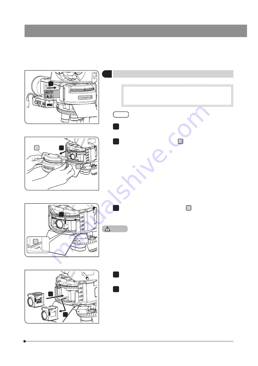
Attaching the fluorescence mirror unit

The fluorescence mirror unit must be attached when the coded 
universal reflected light illuminator (BX3M-URAS-S) is combined 
with the microscope.

When attaching the fluorescence mirror unit, be sure to 
engage the shutter in the light path for safety purpose.

Engage the shutter in the light path.

NOTE

1

Hold the both sides of the cover  a  on the front of the illuminator 
lightly and pull it to the front side.

2

Turn the turret until the position number  b  of the fluorescence mirror 
unit to be replaced comes to the front side, and stop it when the 
clicking sound is heard.

Be careful not to allow your fingers being caught.

3

CAUTION

Hold the side of the fluorescence mirror unit to be replaced, and pull 
it to the front side to remove it.

Insert the new fluorescence mirror unit in the position where the old 
fluorescence mirror unit was removed until it touches the end.

4

5

1

2

a

a

3

4

5

b

Summary of Contents for BXFM

Page 1: ...yourself fully with the use of this system we recommend that you study this manual thoroughly before operating this system and always keep this manual at hand when operating this system Retain this instruction manual in an easily accessible place near the work desk for future reference For details of products included in the configuration of this system see page 10 System Microscope BXFM ...

Page 2: ...cy energy and if not installed and used in accordance with the instruction manual may cause harmful interference to radio communications Operation of this product in a residential area is likely to cause harmful interference in which case the user will be required to correct the interference at his own expense FCC WARNING Changes or modifications not expressly approved by the party responsible for...

Page 3: ...bined 17 4 When BX3M URAS S is combined 17 3 4 Changing between the eyepiece light path and the camera light path 18 3 5 Placing a sample on the stand 18 1 Placing a sample 18 3 6 Selecting the objective 19 3 7 Focusing 20 1 Moving the BXFM frame vertically 20 2 Adjusting the tension of the coarse focusing knob 20 3 Using the rubber cap for fine focusing knob 20 3 8 Adjusting the brightness 21 1 W...

Page 4: ...3 12 Centering the mercury burner 31 3 13 Inserting the reflected light illumination filter 33 1 Using the ND filter lever 33 2 Using the filter 34 4 Various observation methods 36 4 1 Reflected light darkfield observation procedures 36 4 2 Reflected light simple polarization observation procedures 37 4 3 Reflected light differential interference contrast DIC observation procedures 38 4 4 Reflecte...

Page 5: ... reflected light observation 47 3 Adjusting the brightness 48 4 Selecting the illumination pattern 49 4 11 Using the oil immersion objective 50 5 Troubleshooting 51 5 1 Optical systems 51 5 2 Coarse fine focusing 54 5 3 Observation tube 54 6 Specifications 55 7 Main dimension diagram 57 8 Optical performance list UIS2 series 59 9 Assembly 63 9 1 Assembly diagram 63 9 2 Assembly procedures 64 10 Pr...

Page 6: ......

Page 7: ...h the liquid light guide etc U RFL T power supply for mercury burner U RX T power supply for xenon burner Connection of the mercury lamp housing with the power supply TH4 halogen lamp power supply unit Connection of the halogen lamp housing with the power supply BX3M PSLED Power supply for LED Power supply for LED BX3M CB CBFM Control box FM Control box Connection of the cable for motorized nosepi...

Page 8: ...t injured Prevent the microscope from overturning The microscope becomes unstable if the height of the microscope is increased by the accessories mounted on it In this case as this microscope may be overturned take the actions to prevent the microscope from overturning Attach each unit at the appropriate angle If you use the BXFM system in combination with the stand U ST attach the BXFM frame BXFM...

Page 9: ...r BXFM BX3M ILH with combination of the large stand SZ STL the image may fluctuate or blur irregularly when a 50X or higher power objective is used It is recommended to fabricate an exclusive clamping tool to clamp the BXFM frame BXFM F CAUTION Carrying the microscope Hold the BXFM frame and the stand When moving the microscope hold the stand by the bottom with one hand and hold the BXFM frame wit...

Page 10: ... The electromagnetic environment should be evaluated prior to operation of the product Remove the power cord in case of emergency In case of emergency be sure to unplug the power cord from the power cord connector on the product or from the wall power outlet Install the product at the location where you can reach the power cord connector or the wall power outlet at hand to remove the power cord qu...

Page 11: ... the specimen Do not look directly at the light coming out from the objective for a long time since it may cause damage to your eyes Do not expose your skin to the light coming out from the objective for a long time If your skin is exposed to the light coming out from the objective for a long time you may get burned Do not press the micro switch of the MIX slider for reflected light observation U ...

Page 12: ...H100L3 U LH100IR 12V100WHAL L made by PHILIPS Co 7724I 12V100WHAL made by PHILIPS Co 7023 For U LH100HGAPO U LH100HG USH 103OL made by Ushio Co For U HGLGPS SHI 130OL made by Ushio Co Secure the sufficient space around the lamp housing The surface of the lamp housing on the back of the microscope gets very hot Therefore when installing the microscope secure the sufficient space around the lamp hou...

Page 13: ...High temperature Coded universal reflected light illuminator BX3M URAS S High temperature Shutter for coded universal reflected light illuminator BX3M URAS S High temperature DF converter U RCV High temperature 100 W halogen lamp housing for IR U LH100IR High temperature 100 W halogen lamp housing U LH100L 3 High temperature 100 W mercury lamp housing U LH100HG 100 W mercury apo lamp housing U LH1...

Page 14: ...utes or more and replace the lamp See page 74 The mercury burner contains high pressure gas in the tube If you keep using the mercury burner exceeding its lifetime significantly the distortion accumulates in the glass tube to cause the explosion in rare cases In case that the mercury burner explodes Follow the procedures below in case that the mercury burner explodes Unplug the power cord from the...

Page 15: ...mbinable to this product see 2 List of combinable units page 10 Eyepiece Illuminator BXFM frame Hand switch FM control box Power supply for LED Objective Nosepiece Stand Observation tube MIX slider DIC slider for reflected light observation Light source for reflected light illumination Illuminator holder ...

Page 16: ...30 2 U TBI 3 U TR30 2 U TR30IR U ETR 4 U TTR 2 U SWTR 3 U SWETTR 5 U TLU U TLUIR Intermediate attachment U DP U DP1XC U ECA U CA U EPA2 U CPA U OPA U TRU Illuminator holder BX3M ILH BXFM ILHS Illuminator BX3M KMA S BX3M RLA S BX3M RLAS S BX3M URAS S U KMAS Illuminator Option U RCV U LLGAD Light source for reflected light illumination BX3M LEDR U LH100HGAPO U LH100HG U LH100L 3 U LH100IR U HGLGPS P...

Page 17: ...cence Infrared Light sources U LLG150 U LLG300 U RMT Nosepiece U P4RE U P5BDRE U P6RE U 5RE 2 U D6RE U D6RE ESD 2 U D7RE U 5BDRE U D5BDRE U D6BDRE U 5RES ESD U D5BDRES ESD U D6RES U D6BDRES S U D7RES U D5BDREMC U D6REMC U D6BDREMC BX3M RMCBL BD M AD Stand SZ STL U ST Slider for reflected light illumination U 25ND6 U 25ND25 U 25ND50 U 25LBD U 25IF550 U 25L42 U 25FR U 25Y48 U 25LBA U BP1200IR U BP11...

Page 18: ... reflected light observation U MIXR U MIXRCBL Polarizing element U AN 2 U AN360 3 U PO3 U POTP3 U AN360IR U POIR U AN360P Mirror unit U FF U FBF U FDF U FBFL U FWBS U FWGS U FWUS U FDICR Camera adapter U TV0 25XC U TV0 35XC 2 U TV0 5XC 3 U TV0 63XC U TV1XC U TV1X 2 U CMAD3 Hand switch BX3M HS U HSEXP BX3M HSRE TH4 HS Control box BX3M CBFM U CBS Eyepiece WHN10X WHN10X H CROSSWHN10X SWH10X H Objecti...

Page 19: ...13 BXFM MEMO ...

Page 20: ... Y axis knob of the stage page 18 Nosepiece page 19 Coarse Fine focusing knob of the BXFM frame page 20 Brightness control knob of the power supply page 21 Brightness control knob of the power supply page 21 Binocular tube page 23 Diopter adjustment ring page 23 Nosepiece page 19 Coarse Fine focusing knob of the BXFM frame page 20 Aperture diaphragm knob of the reflected light illuminator page 30 ...

Page 21: ...15 BXFM Make a copy of this observation method guide Place it near the microscope so that you use it when operating the microscope TIP 2 3 11 10 5 4 1 7 12 1 6 8 9 ...

Page 22: ...alogen lamp power supply unit TH4 LED lamp housing Main switch of the Power supply for LED BX3M PSLED For details refer to the instruction manual provided with the respective unit 1 2 3 3 2 Turning ON the main switch The reflected LED light illuminator for BF BX3M KMA S is available only for the brightfield observation The other observation methods cannot be selected Select the observation method ...

Page 23: ...rret to select the observation method You can check which No selects which observation method by the inscription pocket a Note that the indicator sheet should be inserted properly in the inscription pocket when attaching the mirror unit Indicator sheet Function BF Brightfield observation BFL Brightfield observation Use when the mercury lamp housing is combined DF Darkfield observation DIC PO Diffe...

Page 24: ...iece 100 Eyepiece 20 Camera 80 Camera 100 U SWTR 3 U TR30IR Eyepiece 100 Eyepiece 0 Camera 0 Shutter Camera 100 U TTR 2 Eyepiece 50 Camera 50 Eyepiece 100 Camera 100 U ETR 4 Eyepiece 100 Camera 100 U SWETR U SWETTR 5 Eyepiece 100 Eyepiece 20 Camera 80 1 3 5 Placing a sample on the stand 1 Placing a sample Place the sample on the stage plate a before observation When using the stand U ST hold the s...

Page 25: ...E to select the objective The nosepiece rotation direction specified by pressing the button can be changed by setting the dip switch on the side of the FM control box BX3M CBFM Before setting the dip switch set the main switch to OFF For settings of the dip switch refer to the instruction manual provided with the BX3M CBFM 1 TIP a When the motorized nosepiece and the hand switch are combined The l...

Page 26: ...he arrow direction to increase the tension If you want to increase the tension of the tension adjustment ring insert the provided Allen screwdriver into the hole b either one of 4 positions of the adjustment ring to increase the tension NOTE TIP Turn the coarse focusing knob a and the fine focusing knob b in the arrow direction to move the BXFM frame downward The objective approaches the sample 1 ...

Page 27: ...side to increase the brightness of the illumination For details of the halogen lamp power supply unit TH4 refer to the instruction manual provided with the unit Engage the ND filter in the light path and adjust the transmittance of the illumination light For details see 3 13 Inserting the reflected light illumination filter page 33 a Turn the light volume adjustment dial a of the light source U HG...

Page 28: ...ar from the upper or lower limit stop position the system may be damaged The intermediate attachment is not available with U TBI 3 If you observe scratches or dirt on the mirror surface in the darkfield observation with U TBI 3 ghosts may appear in some cases 1 NOTE 1 Tilting adjustment 3 9 Adjusting the observation tube When wearing eyeglasses Use the eye shades in the folded down position When n...

Page 29: ...rt a of the eyepiece turn the diopter adjustment ring b to set the index to 0 Perform this operation for right and left eyepieces Adjust the interpupillary distance Place the sample Engage the 10X objective in the light path and turn the coarse fine focusing knobs to bring the sample into focus Change to the 50X objective or higher and turn coarse fine focusing knobs to bring the sample into focus...

Page 30: ... sample Engage the 10X objective in the light path While looking into the eyepiece equipped with the eyepiece micrometer turn the coarse fine focusing knobs to bring the sample into focus Turn the diopter adjustment ring b of the eyepiece not equipped with the eyepiece micrometer to bring the sample into focus 1 2 3 4 When the observation tube is equipped with the interpupillary distance adjustmen...

Page 31: ...phragm increases the contrast furthermore and prevents the flares Note always set to 5 for the darkfield observation When observing the image with eyepiece Observation tube U SWTR 3 U SWETTR 5 Field number 26 5 Others Field number 22 Field diaphragm knob position 4 3 When acquiring the image with camera Set the field diaphragm knob position according to the combination of the image sensor size and...

Page 32: ... 5 inch 1 2 inch 1 1 8 inch 2 3 inch 1 inch 0 5X 2 3 3 5 0 63X 2 2 3 4 1X 2 2 2 3 If the field diaphragm is not centered the area around the field of view may be darkened partially For the centering of the field diaphragm see Centering of the field diaphragm FS page 27 If observing the image with the eyepiece using the field diaphragm settings same as those when acquiring the image with the camera...

Page 33: ...th and place the sample on the stage to bring it into focus approximately NOTE TIP 1 2 3 Centering of the field diaphragm FS Field diaphragm image Field of view of the eyepiece Move the field diaphragm knob field diaphragm lever of the reflected light illuminator to narrow down the diameter of the field diaphragm image to the minimum approximately Picture A 3 Insert the Allen screwdriver in the FS...

Page 34: ...he field diaphragm image inscribes to the field of view Picture C If the field diaphragm image is decentered try centering again 5 Open the field diaphragm until the field diaphragm image becomes almost the same size inscribe as the field of view Picture D 6 5 5 6 6 BX3M RLAS S BX3M URAS S BX3M RLA S ...

Page 35: ...knob The color color bar of the scale b corresponds to the band color c of the objective Aligning the aperture diaphragm knob a position color bar with the band color of the objective engaged in the light path enables to set the aperture diaphragm appropriately Not available for 1 25X and 2 5X objectives The picture shows BX3M RLAS S The same operation parts are also provided to BX3M URAS S When u...

Page 36: ...he aperture diaphragm image to approximately 70 of the field of view If the aperture diaphragm image is displaced from the center of the field of view insert the Allen screwdriver to the AS centering screws 2 pcs of the reflected light illuminator and turn each to adjust the aperture diaphragm image to come to the center of the field of view NOTE TIP 1 2 3 4 5 3 Centering of the aperture diaphragm...

Page 37: ...ttached with the objective remove the objective cap in the light path Pull out the shutter until a clicking sound is heard and remove the shutter from the light path Move the field diaphragm knob to narrow down the field diaphragm BX3M URAS S Position 1 TIP 1 2 NOTE 3 4 5 6 7 8 The centering of the mercury burner is necessary when U LH100HG U LH100HGAPO is combined with the system The mercury burn...

Page 38: ...mirror focusing screw on the back of the lamp housing and turn it to bring the mirror arc image into focus Picture C 11 Turn the burner centering knobs to overlay the arc image with the mirror arc image Picture D During observation turn the collector lens focusing knob to adjust the observation field to become uniform 12 TIP The above picture shows the image of the arc image projected to U CST dur...

Page 39: ...ng the reflected light illumination filter Canceling the link As factory default the ND filter is linked with the selection of the observation method If the brightness is not sufficient when performing the brightfield observation or the DIC observation you can cancel this link Insert the Allen screwdriver into the hole on the left side of the reflected light illuminator to loosen the screw that co...

Page 40: ...servation image U 25Y48 Yellow filter Contrast filter for semiconductor wafer observation U 25ND50 2 Light volume adjustment filter Adjusts the brightness of the light source Transmittance 50 U 25ND25 2 Light volume adjustment filter Adjusts the brightness of the light source Transmittance 25 U 25ND6 2 Light volume adjustment filter Adjusts the brightness of the light source Transmittance 6 U 25FR...

Page 41: ...d raise and slide the cover with the precision screwdriver to open the cover Insert the arbitrary filter in the filter mounting hole b of the slider If the orientation of the filter to use is specified insert the filter so that the filter surface of the light source side faces up 1 2 3 NOTE Insert the precision screwdriver in the notch a and raise and slide the cover with the precision screwdriver...

Page 42: ...age 19 Coarse Fine focusing knob of the BXFM frame page 20 Aperture diaphragm knob of the reflected light illuminator page 30 Field diaphragm knob of the reflected light illuminator page 27 Select the darkfield DF observation 2 Place a sample on the stand 4 Engage the 10X objective in the light path 5 Bring the sample into focus 6 Adjust the interpupillary distance Adjust the diopter 8 9 Adjust th...

Page 43: ...l knob of the power supply page 21 Binocular tube page 23 Diopter adjustment ring page 23 Nosepiece page 19 Coarse Fine focusing knob of the BXFM frame page 20 Aperture diaphragm knob of the reflected light illuminator page 30 Field diaphragm knob of the reflected light illuminator page 27 Select the differential interference contrast polarization DIC POL observation 2 Set the analyzer and the pol...

Page 44: ...age 21 Brightness control knob of the power supply page 21 Binocular tube page 23 Diopter adjustment ring page 23 Nosepiece page 19 Coarse Fine focusing knob of the BXFM frame page 20 Aperture diaphragm knob of the reflected light illuminator page 30 Field diaphragm knob of the reflected light illuminator page 27 Select the differential interference contrast polarization DIC POL observation 2 Set ...

Page 45: ...he power supply page 21 Binocular tube page 23 Diopter adjustment ring page 23 Nosepiece page 19 Coarse Fine focusing knob of the BXFM frame page 20 Aperture diaphragm knob of the reflected light illuminator page 30 Field diaphragm knob of the reflected light illuminator page 27 Place a sample on the stand 3 Engage the 10X objective in the light path 4 Engage the fluorescence mirror unit suitable ...

Page 46: ... light illuminator page 16 Coarse Fine focusing knob of the BXFM frame page 20 Insert the band pass filters for IR U BP1100IR U BP1200IR U 25 4 Turn ON the main switch 1 Filter insertion slot of the reflected light illuminator page 34 Main switch of power supply page 16 Light path selection lever of the trinocular tube page 18 Nosepiece page 19 Nosepiece page 19 Coarse Fine focusing knob of the BX...

Page 47: ... Binocular tube page 23 Diopter adjustment ring page 23 Nosepiece page 19 Coarse Fine focusing knob of the BXFM frame page 20 Aperture diaphragm knob of the reflected light illuminator page 30 Field diaphragm knob of the reflected light illuminator page 27 Select the brightfield BF observation 2 Place a sample on the stand 4 Engage the 10X objective in the light path 5 Bring the sample into focus ...

Page 48: ...le into focus approximately If the cover or the dummy slider is attached to the analyzer insertion slot a or the polarizer insertion slot b remove it Insert the analyzer in the analyzer insertion slot a Analyzer insertion position Light path First level pulled out Empty hole Second level pressed in Analyzer Insert the polarizer U PO3 or U POTP3 in the polarizer insertion slot b with the display su...

Page 49: ...ring the sample into focus approximately 1 2 a 3 7 Turn the dial to adjust the analyzer Observation with crossed Nichols Align the white circle index c of the dial with the white line d Observation without crossed Nichols Turn the dial while looking at the observation image and align it with the position where you can view the desired observation image The crossed Nichols means the state that the ...

Page 50: ...PLFLN MPLFLN BD series MPLAPON series UIS UMPlanFl UMPlanFl BD series MPlanApo20X 100X MPlanApo100XBD 2 4 8 Inserting the DIC slider Push in the DIC slider to the second level position where the clicking sound is heard DIC slider position Light path First level pulled out OUT Second level pressed in IN 1 1 Inserting the DIC slider This operation is necessary when the DIC slider for reflected light...

Page 51: ...contrast in the gray sensitive color with the highest sensitivity If you select the magenta sensitive color for the background color even a small phase difference can be viewed by a variation of the color If you want to select the magenta sensitive color for the background color when using U DICRH engage the polarizer U POTP3 in the light path For details see 4 7 Setting the analyzer and the polar...

Page 52: ...necessary when the coded universal reflected light illuminator BX3M URAS S is combined Push in the shutter to the second level position where the clicking sound is heard Shutter position Light path First level pulled out OUT Second level pressed in IN 1 1 ...

Page 53: ...ight observation a a b c The state whether the MIX slider for reflected light observation is engaged in or removed from the light path can be checked by the POSITION indicator a of the hand switch BX3M HS If you press the ON OFF button a of the hand switch BX3M HS to set it to ON the illumination of the MIX slider for reflected light observation U MIXR turns ON State Indicator b c Function ON Turn...

Page 54: ...redetermined quantity Long press Darken continuously Short press Brighten by predetermined quantity Long press Brighten continuously Indicator The light intensity state can be checked by the indicator b Brightness OFF Light intensity value 0 Brightness Maximum Light intensity value 100 Turns ON in blue Turns ON in white Turns OFF 1 3 Adjusting the brightness b ...

Page 55: ... the MODE button a of the hand switch BX3M HS to select the illumination pattern The indicator b turns ON according to the illumination pattern Operation Function Short press Changes the illumination pattern Long press Short press while the illumination pattern is rotating automatically The illumination pattern rotates automatically clockwise The automatic rotation stops Long press Short press The...

Page 56: ...ple into focus using the fine focusing knob If bubbles are contained in the oil the visibility of the image is deteriorated Check that the bubbles are not contained in the oil To remove bubbles turn the nosepiece slightly and move the oil immersion objective back and forth once or twice After use lower the stage turn the nosepiece 90 and remove the objective attached with the oil from the sample T...

Page 57: ...ve the analyzer or the polarizer from the light path 42 Light path selection lever of the trinocular tube is at the position Set the light path selection lever of the trinocular tube to the or the position 18 The observation method selector knob or lever or the turret is at the halfway position Select the observation method selector knob or lever or the turret surely 16 The shutter is engaged in t...

Page 58: ...t the correct position Stop the ND filter lever at the position where the clicking sound is heard 33 The ND filter is not linked completely Set the ND filter correctly whether to link or cancel 33 The lamp is not attached correctly Push in the terminal of the halogen bulb completely until it touches the end 74 The analyzer and the polarizer are not inserted correctly Engage the analyzer and the po...

Page 59: ...ight Replace with another sample 18 k The observation image shifts when defocusing The nosepiece is not attached correctly Push in the nosepiece along the mounting dovetail until it touches the end and secure it 70 The objective is not correctly engaged in the light path Turn the nosepiece until the clicking sound is heard and engage the objective in the light path 19 The aperture diaphragm is nar...

Page 60: ...se focusing knob is tightened too firmly Loosen the tension adjustment ring so that the tension of the coarse focusing knob becomes the appropriate tightness 20 b The stage descends on its own weight Or the sample is defocused due to the slip of the coarse focusing knob The tension adjustment ring of the coarse focusing knob is loosened too much Tighten the tension adjustment ring so that the tens...

Page 61: ...field darkfield DIC simple polarization observations coded type built in LED light source BX3M URAS S For brightfield darkfield simple polarization fluorescence infrared observations coded type detachable mirror unit attachable to 4 positions U KMAS For brightfield DIC simple polarization observations Field number 26 5 Light source for reflected light illumination LED lamp housing BX3M LEDR White ...

Page 62: ...ed type U D5BDREMC 5 holes darkfield observation available detachable slider U D6REMC 6 holes detachable slider U D6BDREMC 6 holes darkfield observation available detachable slider Slider For differential interference contrast U DICR Standard type U DICRH High resolution type U DICRHC High contrast type For MIX U MIXR Equipped with LED ring illumination light control by hand switch Operating envir...

Page 63: ...ange Optical axis Nosepiece mount surface Objective mount surface Specimen surface 57 BXFM 7Main dimension diagram BXFM frame BXFM F Provided with Illuminator mounting holder S BXFM F BXFM ILHS 4 M8 depth 8 4 M4 depth 9 4 M4 depth 7 Movable range ...

Page 64: ...der mount surface Movable range Optical axis Nosepiece mount surface Objective mount surface Specimen surface Optical axis 58 Provided with Illuminator Mounting Holder Assist spring for BXFM BXFM F BX3M ILH BXFM ILHSPU ...

Page 65: ...omat for brightfield darkfield 5X 10X 20X 50X 100X MPLFLN Plan Semi Apochromat 1 25X 1 2 5X 1 5X 10X 20X 40X 2 50X 100X MPLFLN BD Plan Semi Apochromat BD 5X 10X 20X 50X 100X 150X MPLFLN BDP Plan Semi Apochromat for reflected light polarization 5X 10X 20X 50X 100X LMPLFLN Long working distance Plan Semi Apochromat 5X 10X 20X 50X 100X LMPLFLN BD Long working distance Plan Semi Apochromat for brightf...

Page 66: ...22 1000X 0 27 MPLFLN BD Plan Semi Apochromat for brightfield darkfield OFN26 5 MPlanFLN BD 5X 0 15 12 0 50X 4 4 50X 5 3 10X 0 30 6 5 100X 2 2 100X 2 65 20X 0 45 3 0 0 200X 1 1 200X 1 33 50X 0 80 1 0 0 500X 0 44 500X 0 53 100X 0 90 1 0 0 1000X 0 22 1000X 0 27 150X 0 90 1 0 0 1500X 0 15 1500X 0 18 MPLFLN BDP Plan Semi Apochromat for reflected light polarization OFN26 5 MPlanFLN BDP 5X 0 15 12 0 50X ...

Page 67: ...00X 2 65 LCPLN IR Plan Achromat for observation through glass OFN22 LCPlanN 2 20X 0 45 8 3 0 1 2 200X 1 1 200X 1 33 50X 0 65 4 5 0 1 2 500X 0 44 500X 0 53 100X 0 85 1 2 0 0 7 1000X 0 22 1000X 0 27 LCPLFLN LCD Long working distance Plan Semi Apochromat OFN26 5 LCPlanFLN 2 20X 0 45 7 4 8 3 0 1 2 200X 1 1 200X 1 33 50X 0 70 2 2 3 0 1 2 500X 0 44 500X 0 53 100X 0 85 0 9 1 2 0 0 7 1000X 0 22 1000X 0 27...

Page 68: ...depth increases when the aperture diaphragm is narrowed down and decreases when the numerical aperture of the objective becomes larger Field number Indicates the diameter of the image area visible by the eyepiece in mm Actual field Indicates the diameter of the field area on the sample surface in mm Ex None UIS objective N UIS2 objective None Achromat Corrects the aberration by 2 wavelengths blue ...

Page 69: ...Light source for reflected light illumination Reflected light illuminator Reflected light illuminator Brightfield darkfield objective BXFM frame BXFM F Brightfield objective adapter Cable for motorized nosepiece Nosepiece For the polarization observation refer to the instruction manual provided with the unit Stand U ST SZ STL Assist spring for BXFM BXFM ILHSPU Illuminator holder for BXFM S BXFM IL...

Page 70: ...ce position clamp the illuminator holder by attaching it completely to the bottom and right side of concave area of the BXFM frame 1 TIP When using the illuminator holder for BXFM BX3M ILH attach the assist spring for BXFM if required Place the BXFM frame BXFM F upside down Align the mounting hole c of the BXFM frame BXFM F with the screw holes d 4 positions of the assist spring for BXFM BXFM ILHS...

Page 71: ...umn of the stand 1 Turn the knob b of the BXFM frame BXFM F to loosen it Insert the BXFM frame into the column of the stand stop it at the position you want to secure it and turn the knob of the BXFM frame BXFM F to tighten it 2 3 Raise the drop prevention ring until it touches the bottom of the BXFM frame and turn the knob a to tighten it 4 3 2 b ...

Page 72: ...lder for BXFM BX3M ILH to the connector of the FM control box BX3M CBFM For connection of the cable for motorized nosepiece BX3M RMCBL with the FM control box BX3M CBFM refer to the instruction manual provided with the BX3M CBFM 1 2 3 b c 2 4 Attaching the control box for coded function a d e f b c d a d 3 4 2 The control box for coded function U CBS must be attached when combining the coded refle...

Page 73: ... of the reflected light illuminator with the mounting screw holes b of the illuminator holder for BXFM BX3M ILH at first place the reflected light illuminator on the mounting surface at the slightly right position Then push the reflected light illuminator to the end of the left side This is the correct attaching position While pushing the reflected light illuminator to the end of the left side tig...

Page 74: ... The super widefield observation tube is equipped with positioning grooves on both eyepiece sleeves Be sure to attach the eyepieces by aligning both eyepiece positioning pins with the grooves 1 NOTE 1 Attaching the eyepiece micrometer The eyepiece micrometer can be attached to WHN10x H Purchase the micrometer with the size Ø24 mm and thickness 1 5 mm Remove the built in micrometer frame from the e...

Page 75: ...nosepiece mounting holes 1 1 When the motorized nosepiece and the hand switch are combined Attach the magnet sheet corresponding to the objectives attached in 1 to the OB indicator display pocket a of the hand switch BX3M HS The magnet sheet is provided with the hand switch BX3M HS a ...

Page 76: ... the connector of the control box for coded function U CBS When attaching or detaching the nosepiece attached with the cable be sure to remove the cable from the connector in advance If you want to change the nosepiece to the motorized nosepiece when using the system combined with the manual nosepiece remove the reflected light illuminator together when removing the manual nosepiece In order to co...

Page 77: ...ng knob a to secure the slider When the MIX slider for reflected light observation is attached Connect the cable to the connector of the FM control box BX3M CBFM Lay out the cable using the provided cable holders so as not to interfere the operations of the product The cable holders are provided with the cable for U MIXR U MIXRCBL For connection of the cable for the MIX slider with the FM control ...

Page 78: ...radiation fin faces up Do not light the mercury burner when the lamp housing is not attached to the microscope because the UV rays in its light are harmful to your eyes Tighten the mounting screws a 2 positions of the reflected light illuminator using the Allen screwdriver If the reflected LED lamp housing is attached connect the cable to the connector on the back of the power supply for LED BX3M ...

Page 79: ... DF converter into the light source mounting hole of the reflected light illuminator until it touches the end When attaching the mercury lamp housing attach it so that the radiation fin faces up Tighten the mounting screws b 2 positions of the reflected light illuminator using the Allen screwdriver If the reflected LED lamp housing is attached connect the cable to the connector on the back of the ...

Page 80: ... lamp socket in the arrow direction by 90 3 a b c d While pressing down the bulb fixing lever a hold the halogen bulb b wrapped with gauze etc and insert the terminal c until it touches the pin position d Place the bulb fixing lever a carefully to the original position to secure the bulb Be careful not to touch the bulb directly with your hand and avoid leaving fingerprints or stains on the lamp O...

Page 81: ...until the bulb the lamp housing and areas around the lamp housing are sufficiently cooled down and replace the old bulb with the applicable bulb 5 CAUTION 2 4 c b a b 1 Hold the upper section of the lamp housing and pull it upward to remove the socket part To prevent malfunctions do not hold the lamp housing by the centering knobs a 2 NOTE Place the socket part so that the radiation fin b faces do...

Page 82: ... fingerprints or stains on the lamp Otherwise the burner may be exploded due to the glass distortion caused by the stains If fingerprints or stains are attached to the burner clean it by wiping gently with a piece of cleaning paper slightly moistened with absolute alcohol Tighten the burner clamping screws 2 pcs of the socket part Align the external surfaces of the lamp housing with those on the s...

Page 83: ...des of the cover a on the front of the illuminator lightly and pull it to the front side 2 Turn the turret until the position number b of the fluorescence mirror unit to be replaced comes to the front side and stop it when the clicking sound is heard Be careful not to allow your fingers being caught 3 CAUTION Hold the side of the fluorescence mirror unit to be replaced and pull it to the front sid...

Page 84: ... fluorescence mirror unit is secured firmly Without this operation the fluorescence mirror unit may be attached being tilted 6 Insert the indicator sheet corresponding to the fluorescence mirror unit which was inserted in 5 in the inscription pocket c The indicator sheet is provided with BX3M URAS S 7 Hold the knob a of the cover and close the cover 8 6 7 c 8 a a ...

Page 85: ...ng time exceeds 20 000 hours of use 2 Lamp does not light sometimes even though the main switch is turned ON Only when using the halogen bulb 3 Dirt or substances are attached around the main switch 4 The light flickers if you move a lamp cable or illumination devices 5 Lamp cable is unusually hot to the touch 6 Burning or smoke odor 7 The light still flickers even though the lamp is replaced Only...

Page 86: ...lly the power supply cord which is approved by one of the agencies mentioned in Table 1 please use replacements approved by any other equivalent and authorized agencies in your country Country Agency Certification mark Country Agency Certification mark Argentina IRAM Italy IMQ Australia SAA Japan JET Austria ÖVE Netherlands KEMA Belgium CEBEC Norway NEMKO Canada CSA Spain AEE Denmark DEMKO Sweden ...

Page 87: ...ic Cables BASEC BASEC HAR 10 10 30 N V KEMA KEMA KEUR HAR 10 30 30 SEMKO AB Svenska Elektriska Materielkontrollanstalter SEMKO HAR 10 10 50 Österreichischer Verband für Elektrotechnik ÖVE ÖVE HAR 30 10 50 Danmarks Elektriske Materialkontroll DEMKO DEMKO HAR 30 10 30 National Standards Authority of Ireland NSAI NSAI HAR 30 30 50 Norges Elektriske Materiellkontroll NEMKO NEMKO HAR 10 10 70 Asociacio...

Page 88: ...AX8562 03 Distributed by Manufactured by Shinjuku Monolith 2 3 1 Nishi Shinjuku Shinjuku ku Tokyo 163 0914 Japan www olympus global com Issued in May 2019 ...

Reviews: