background image

15

BXFMA

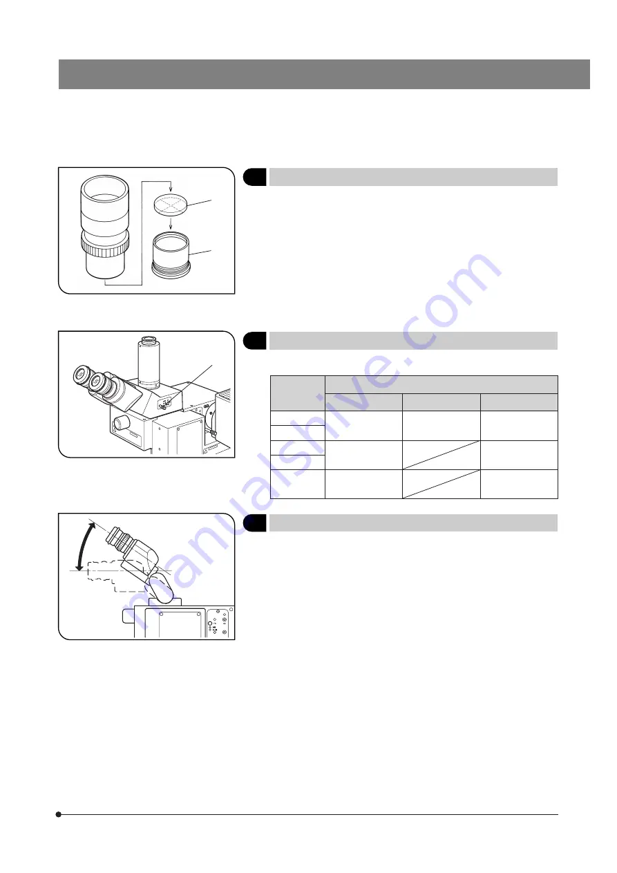
Fig. 15

4

    Using Eyepiece Micrometer Disks

(Fig. 15)

Eyepiece micrometer disks can be inserted into the WHN10X-H (or
WHN10X) eyepieces.
However, if the eyepiece does not have the helicoid adjustment facility
and your eyesight is poor, you may have difficulties in focusing on the
eyepiece micrometer disk. In this case, it is recommended to look into
the eyepiece through your eyeglasses.
Use 24 mm dia. x 1.5 mm thick micrometer disks.
Following Fig. 15, unscrew the micrometer mounting frame 

2

 from the

eyepiece and place a micrometer disk 

1

 into the mounting frame. Reat-

tach the micrometer mounting frame in the original position.

@

²

Fig. 16

Fig. 17

5

    Selecting the Light Path of Trinocular Observation Tube

(Fig. 16)

Slide the light path selector knob 

1

 to select the desired light path.

Trinocular
Tube

Light Path Selector Position

Pushed in

Middle position

Pulled out

U-TR30-2

Binocular 100%

Binocular 20%
TV, photo 80%

TV, photo 100%

U-SWTR-3

U-ETR-4

Binocular 100%

TV, photo 100%

U-SWETR

U-SWETTR2

Binocular 100%

Binocular 20%
TV, photo 80%

6

    Adjusting the Tilt (with the U-TBI3/SWETTR-5)

(Fig. 17)

}Adjust the height and tilt of the observation tube to obtain the most com-

fortable viewing position.
Holding the binocular section with both hands, raise or lower it to the
desired position.

# Never attempt to force the binocular section past the upper or lower

stop position. Applying excessive force could destroy the limiting
mechanism.

# The U-TBI3 cannot be used in combination with any intermediate

attachment.

@

Summary of Contents for BXFMA

Page 1: ...MA To ensure the safety obtain optimum performance and to familiarize yourself fully with the use of this system we recommend that you study this manual thoroughly before operating the system Retain t...

Page 2: ......

Page 3: ...it its full performance If you are going to assemble the microscope yourself please read Chapter 8 ASSEMBLY pages 23 to 28 carefully 1 Selecting the Observation Light Path 2 Centering the Field Iris D...

Page 4: ......

Page 5: ...e focusing unit observation method switch and aperture iris diaphragm AS mechanism Be sure to release the transport lock of these three modules before assembly and engage the transport lock before the...

Page 6: ...ope stops operating Should this happen set the main switch to OFF and then I ON again 3 The surface of the lamp housing on the side of the illuminator becomes very hot When installing the system leave...

Page 7: ...le absolute alcohol Since the absolute alcohol is highly flammable it must be handled carefully Be sure to keep it away from open flames or potential sources of electrical sparks for example electrica...

Page 8: ...Observation tube U BI30 2 U TR30 2 U TBI3 U TUL etc Active AF Unit U AFA1M Motorized Revolving Nosepiece U D5BDREMC U D6REMC U P5REMC U D5BDREM U D6REM Objective Connection cable 50 pin Connection ca...

Page 9: ...ng screws x 4 Aperture iris diaphragm lock screw Page 11 Auxiliary ring Note 1 Aperture iris diaphragm centering screws Page 11 Field iris diaphragm centering screws Page 10 Field iris diaphragm lever...

Page 10: ...nstruction manual DF Darkfield button Focus Adjustment Knob Interface U IFFH U FH connector Power Supply Unit TH4 For details refer to the separate instruction manual Main switch BF Brightfield button...

Page 11: ...Fine Coarse switch button Page 12 Focusing motor ON OFF Objective Down button Page 12 F C selector Transmitted reflected light switch button Option Objective Up button Page 12 Objective escape return...

Page 12: ...pecimen on the speci men table Engage the 10X objective in the light path 6Revolving nosepiece button 3PC command Bring the specimen in focus 7Objective Up Down buttons or 8Focus adjustment knob 3PC c...

Page 13: ...ator with Motorized Focusing Unit BXFMA F Make a photocopy of the observation procedure pages and post it near your microscope 2 3 4 5 6 7 8 9 a b c d e Motorized Revolving Nosepiece Focus Adjustment...

Page 14: ...ary lever 4 is inserted as required 1 Press the BF button 1 of the hand switch to select the reflected light brightfield light path 2 Press the objective button 3 of the hand switch to engage the 10X...

Page 15: ...e and bring the specimen into approximate focus It is recommended to use a highly reflective specimen such as a mirror to facilitate viewing the aperture iris diaphragm image 3 Remove an eyepiece look...

Page 16: ...ig 8 Adjust the lower hardware limit using the following procedure The lower hardware limit of the objective has been set to the lower limit of the stroke before the system left the factory During adj...

Page 17: ...conversion filter for turning the illumi nation light to daylight For use in general observation or color photomicrography 32IF550 Green filter for giving contrast to a monochrome image For use in mo...

Page 18: ...op of the eyepiece until clearly defined double crosslines can be seen in the field of view Figs 12 13 2 Looking through the right eyepiece rotate the focus adjustment knobs to bring the specimen and...

Page 19: ...5 Selecting the Light Path of Trinocular Observation Tube Fig 16 Slide the light path selector knob 1 to select the desired light path Trinocular Tube Light Path Selector Position Pushed in Middle pos...

Page 20: ...Microscopy Tab Check only EPI BF reflected light brightfield observation and EPI DF reflected light darkfield observation 4 Mirror unit setting Mirror Unit Tab Enter BF or DF 6 Turret optical device a...

Page 21: ...light path selector lever of trinocular tube is in an intermediate position Set the knob according to the obser vation method The revolving nosepiece is not correctly mounted Attach the revolving nose...

Page 22: ...or software lower limit to an optimum height Re place the specimen within the focusing range 4 Observation Tube a Field of view of one eye does not match that of the other The interpupillary distance...

Page 23: ...is 3 mm sec Full stroke range 5 mm 2 mm down and 3 mm up from the standard focusing position 7 mm including the escape stroke Revolving nosepiece Motorized revolving nosepiece U D5BDREMC U D6REMC U P...

Page 24: ...D Plan Semi Apochromat FN26 5 LMPlanFLN LMPLFLN BD Brightfield darkfield long WD Plan Semi Apochromat FN26 5 LMPlanFLN BD 1 25X 0 04 3 5 8 39 12 5X 870 17 6 2 5X 0 08 10 7 4 19 25X 220 8 8 25X 220 10...

Page 25: ...5 LCPlanFLN 20XLCD 0 45 7 4 8 3 0 1 2 0 75 200X 5 2 1 1 200X 5 2 1 33 50XLCD 0 70 2 2 3 0 1 2 0 48 500X 1 6 0 44 500X 1 6 0 53 100XLCD 0 85 0 9 1 2 0 0 7 0 39 1000X 0 79 0 22 1000X 0 79 0 27 Optical...

Page 26: ...top of specimen and the front lens of objective Number of aperture NA Important figure determining the objective characteristics resolution focal depth and bright ness Resolution Increases in proport...

Page 27: ...ent pages Please also refer to the instruction manuals provided with the modules For the connection of modules see also Chapter 1 System Diagram on page 4 Eyepiece WHN10X FN 22 35WHN10X FN 22 SWH10X H...

Page 28: ...e illuminator left side panel has two posi tioning dents 2 To obtain the standard position clamp the illuminator by pushing it up and rightwards by using the dents Installation by the Bottom Side Pane...

Page 29: ...e Specimen surface standard focusing position 6 M8 Depth 10 51 77 114 7 7 2 15 10 72 92 113 92 148 20 56 6 M8 Depth 10 Concave 10 Concave 4 31 63 50 113 R 8 61 67 142 67 61 5 68 72 4 R10 4 R10 Bottom...

Page 30: ...the BXFMA system Changing the On Board DIP SW Setting Fig 20 Leave all other switch segments than those listed below to OFF S2 Set segment No 2 and 3 to ON S3 Set segment No 2 to ON S3 Segment No 5 is...

Page 31: ...the pin sections 7 on the lamp socket Gently release the bulb clamping lever to the original position to secure the bulb To prevent reduced bulb life or cracking do not touch the bulb with bare hands...

Page 32: ...in fits into the groove at the bottom of the eyepiece sleeve The super widefield trinocular observation tube is equipped with a positioning notch on both eyepiece sleeves Make sure that the positionin...

Page 33: ...time has exceeded 20 000 hours 2 Lamp does not light sometimes even though the main switch is set to on Except discharge burners 1 3 Illumination flickers when you move the lamp cable or lamp housing...

Page 34: ...MEMO...

Page 35: ......

Page 36: ...ny 3500 Corporate Parkway P O Box 610 Center Valley PA 18034 0610 U S A One Corporate Drive Orangeburg NY 10962 U S A 491B River Valley Road 12 01 04 Valley Point Office Tower Singapore 248373 31 Gilb...

Reviews: