APPLIED OPERATIONS
/Image Acquisition
OPERATION INSTRUCTIONS
2 - 1 6
Page
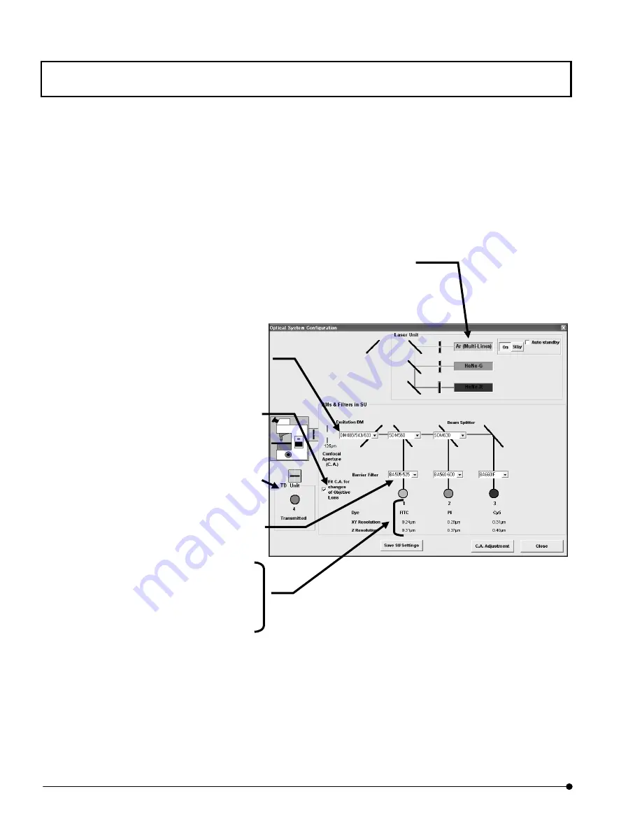
2. Click the <Scan Unit> button at the bottom of the panel. The window as shown below
will appear.
Fig. 2-7 [Optical System Configuration] Window
3. To change the displayed filter types, use the [Excitation DM], [Beam splitter] and/or
[Barrier Filter] drop-down lists.
4.
After completing the filter setup, click the <Close> button.
[TD Unit] group box
Shows the transmitted light detection.
[Excitation DM] and [Beam splitter] drop-down
lists
Change the excitation filter and beam splitter of
each channel.
[Barrier Filter] drop-down list
Changes the barrier filter of each channel.
[Dyes]
Shows the dyeing method set for each channel.
[
XY Resolution]
Shows lateral resolution for each channel.
[Z Resolution]
Shows the Z resolution set for each channel.
[Laser Unit] group box
Shows the type of laser to be used. (With the laser combiner operation, the laser type is set
and displayed automatically.) When the <On> button is pressed-in, the laser is oscillating the
beam. When the <Stby> button is pressed-in, the laser is not oscillating. When the [Auto
standby] check box is checked, the [After] text box appears below it. When not using laser for
a long time, in order to suppress useless electric-power consumption, we recommend you
making <Stby> mode. The laser oscillation stops when the time shown in this box has
elapsed after the end of laser scanning. The laser oscillation stops when the time shown in
this box has elapsed after the end of laser scanning. The laser is suspended as standby
mode (using Ar or Kr-laser) or the laser oscillation stops(using UV-Ar laser) When the time
shown in this box has elapsed after the end of laser scanning.
[Fit C.A. for change of Objective Lens]
Check box
In case of check this box, Confocal
Aperture diameter is set with switching the
objective.


