Setup
/ Cable connections
III.
PACKING DETAILS CHECK
III.
3 - 1
Page
3 Setup
Setup of this system is normally executed by our service personnel. This section describes setup procedures
briefly.
3-1 Cable connections
1.
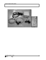
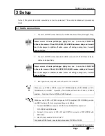
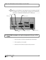
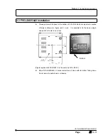
Connect LD-LDPSU inline cable to FV5-LD405 and fasten cable pull-stopper firmly.
Fasten screws of cable pull-stopper tightly for sure. In case that LD-LDPSU
inline cable comes off from FV5-LD405, FV5-LD405 becomes shaky and it would
lead to breakage. In addition, if cable comes off during running time, it would
cause a failure.
2.
Connect LD-LDPSU inline cable to LD-HEAD connector of FV5-LDPSU and fasten
cable pull-stopper firmly.
Fasten screws of cable pull-stopper tightly for sure. In case that LD-LDPSU
inline cable comes off from FV5-LDPSU, FV5-LD405 becomes shaky and it would
lead to breakage. In addition, if cable comes off during running time, it would
cause a failure.
3.
Insert power cord into power cord connector of FV5-LDPSU.
When you use FV300 or FV500, connect FV-COMB cable from FV5-COMB(2) or FV5-
COMBA with FV5-LDPSU. Operation of FLUOVIEW software from FV300 or FV500 is
possible. For detail, refer to FV300 or FV500 manual.
When you use FV300 or FV500 and you set AOTF combiner (FV5-COMBA), you can
use REX function at the following connections and settings.
1. Connect BLANKING connector of FV5-LCU and ANALOG connector of
FV5-LDPSU with BNC cable.
2. Connect UV connector of FV5-LCU and DIGITAL connector of FV5-LDPSU with
BNC cable.
3. Set UV rotary switch of FV5-LCU to "1".
For details of REX function see instruction manual of FV300 or FV500.
NOTE
NOTE
TIP
TIP
Summary of Contents for FV5-LD405
Page 2: ......
Page 8: ......
Page 10: ......
Page 20: ......
Page 22: ......
Page 40: ......
Page 42: ......
Page 44: ......
Page 46: ......
Page 48: ......
Page 50: ......
Page 52: ......
Page 54: ......
Page 62: ......
Page 64: ......
Page 66: ......
Page 74: ......
Page 76: ......
Page 78: ......
Page 80: ......
Page 82: ......
Page 84: ......
Page 86: ......
Page 90: ......
Page 91: ......

