DMTA029-01EN, Rev. E, December 2017
Scanner Assembly and Setup
43
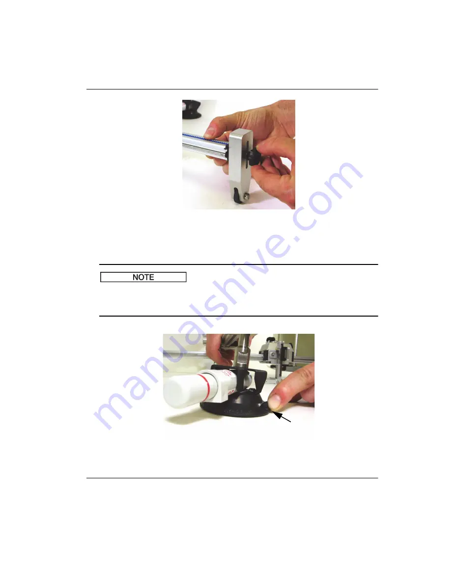
Figure 2
‑
39 Tightening the thumbscrew on the Y
‑
axis support
5.
Tighten the pivot locks on the two mounting pods.
To remove a scanner with manual cups from the inspection surface, push up against
the tab on the suction cups, as shown in Figure 2-40 on page 43. To remove a scanner
using a vacuum generator, turn off the air supply to the generator.
Figure 2
‑
40 Disengaging a manual
‑
type suction cup from the surface
NOTE
Summary of Contents for GLIDER
Page 6: ...DMTA029 01EN Rev E December 2017 List of Abbreviations vi...
Page 16: ...DMTA029 01EN Rev E December 2017 Important Information Please Read Before Use 10...
Page 18: ...DMTA029 01EN Rev E December 2017 Introduction 12...
Page 54: ...DMTA029 01EN Rev E December 2017 Chapter 2 48...
Page 62: ...DMTA029 01EN Rev E December 2017 Chapter 4 56...
Page 70: ...DMTA029 01EN Rev E December 2017 Chapter 5 64...
Page 76: ...DMTA029 01EN Rev E December 2017 List of Tables 70...


