DMTA029-01EN, Rev. E, December 2017
Scanner Assembly and Setup
37
Before you install the new probe on the wedge, ensure that there is a sufficient
amount of couplant between the probe and the wedge.
9.
Tighten the four screws that hold the probe on the wedge.
Do not overtighten the screws; overtightening might crack the wedge.
10. Reinstall the yoke on the wedge.
11. Reinstall the probe assembly on the bearing arm.
2.2.7
Changing an Encoder
An encoder only needs to be changed if it malfunctions.
To change an encoder
1.
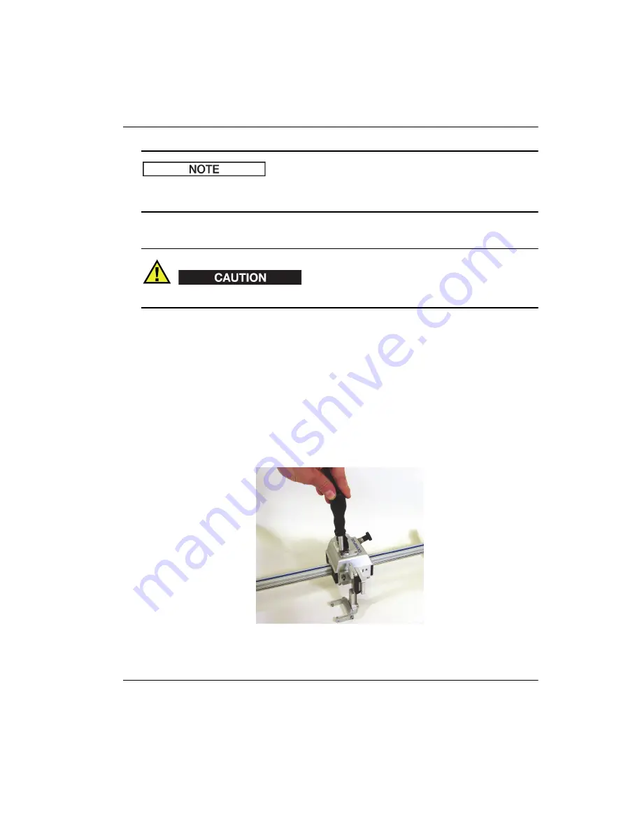
Remove the two screws (see Figure 2-31 on page 37).
Figure 2
‑
31 Removing the encoder screws
NOTE
CAUTION
Summary of Contents for GLIDER
Page 6: ...DMTA029 01EN Rev E December 2017 List of Abbreviations vi...
Page 16: ...DMTA029 01EN Rev E December 2017 Important Information Please Read Before Use 10...
Page 18: ...DMTA029 01EN Rev E December 2017 Introduction 12...
Page 54: ...DMTA029 01EN Rev E December 2017 Chapter 2 48...
Page 62: ...DMTA029 01EN Rev E December 2017 Chapter 4 56...
Page 70: ...DMTA029 01EN Rev E December 2017 Chapter 5 64...
Page 76: ...DMTA029 01EN Rev E December 2017 List of Tables 70...


