DMTA029-01EN, Rev. E, December 2017
Scanner Assembly and Setup
39
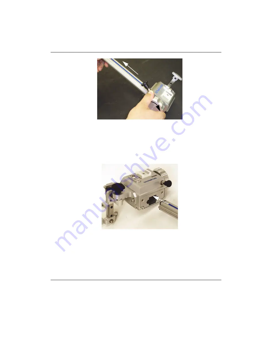
Figure 2
‑
33 Removing the axis
2.
Align the new axis with the opening in the encoder module (see Figure 2-34 on
page 39).
The rack gear must align with the pinion gear in the module.
Figure 2
‑
34 Aligning the new axis
3.
Turn the increment knob to move the axis into the module (see Figure 2-35 on
page 40).
Summary of Contents for GLIDER
Page 6: ...DMTA029 01EN Rev E December 2017 List of Abbreviations vi...
Page 16: ...DMTA029 01EN Rev E December 2017 Important Information Please Read Before Use 10...
Page 18: ...DMTA029 01EN Rev E December 2017 Introduction 12...
Page 54: ...DMTA029 01EN Rev E December 2017 Chapter 2 48...
Page 62: ...DMTA029 01EN Rev E December 2017 Chapter 4 56...
Page 70: ...DMTA029 01EN Rev E December 2017 Chapter 5 64...
Page 76: ...DMTA029 01EN Rev E December 2017 List of Tables 70...


