DMTA029-01EN, Rev. E, December 2017
Chapter 2
46
To remove a magnetic pod from the inspection surface, simply turn the magnetic-
activation lever to the “off” position.
2.4
Setting Up the Scanner for Inspection
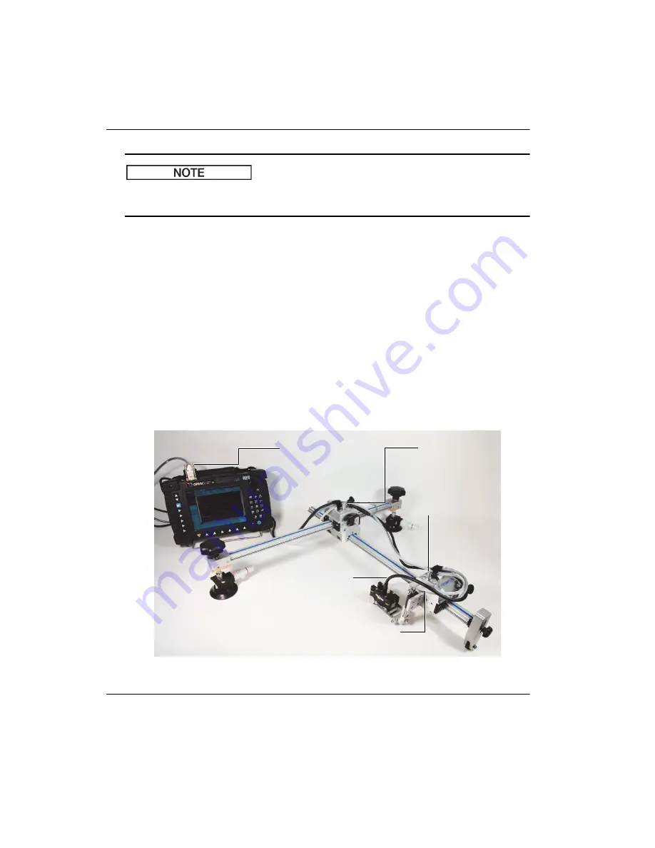
Before starting the inspection, it is necessary to ensure that the scanner’s connections
(such as the probe or transducer cable, encoder cable, and water tube) are correctly
made on the main equipment components.
To set up the scanner for inspection
1.
Use the dedicated cable to connect the probe or transducer to the acquisition unit.
2.
Connect the water tube between the wedge and the water-supply unit (see
Figure 2-43 on page 46).
3.
Connect the encoders to the acquisition unit.
Figure 2
‑
43 Scanner setup
NOTE
Acquisition unit
Cable between probe (or
transducer) and acquisition
unit
Tube between wedge and water
supply
Encoder 1 (X)
connector
Encoder connector on
acquisition unit (may differ
from example shown)
Encoder 2 (Y)
connector
Summary of Contents for GLIDER
Page 6: ...DMTA029 01EN Rev E December 2017 List of Abbreviations vi...
Page 16: ...DMTA029 01EN Rev E December 2017 Important Information Please Read Before Use 10...
Page 18: ...DMTA029 01EN Rev E December 2017 Introduction 12...
Page 54: ...DMTA029 01EN Rev E December 2017 Chapter 2 48...
Page 62: ...DMTA029 01EN Rev E December 2017 Chapter 4 56...
Page 70: ...DMTA029 01EN Rev E December 2017 Chapter 5 64...
Page 76: ...DMTA029 01EN Rev E December 2017 List of Tables 70...


