background image

DMTA020-01EN, Rev. D, September 2016

Chapter 2


18

2.2

Wedges

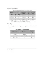
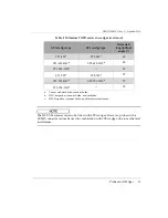
Table 4 on page 18 describes the wedges used for inspections made with the HST-X04 
scanner.

10

 3

 0.125

 C563-XX

a

 ST1

 3/8 - 32 

 6

0.25

 C544-XX

a

 ST1

 3/8 - 32 

15

 3

 0.125

 C564-XX

a

 ST1

 3/8 - 32 

a.

The XX part of the transducer part number indicates that two types of connectors are 
available: SM (Microdot connectors) or SL (LEMO 00 connectors)

Table 4  Miniature TOFD screw-in wedges 

ST1 wedge type

ST2 wedge type

Refracted 

longitudinal 

angle (°)

ST1-45L

a

 ST2-45L

a

 45

 ST1-45L-IHC

b

 ST2-45L-IHC

b

 45

 ST1-45L-IHS

c

45

Table 3  Miniature screw-in TOFD transducers 

(continued)

Frequency

Nominal 

element size

Transducer part 

numbers

Case 

type

Case thread 

pitch

MHz

mm

Inches

Summary of Contents for HST-X04

Page 1: ...anual This instruction manual contains essential information on how to use this Olympus product safely and effectively Before using this product thoroughly review this instruction manual Use the produ...

Page 2: ...ensure the accuracy of the information contained therein and corresponds to the version of the product manufactured prior to the date appearing on the title page There could however be some differenc...

Page 3: ...Words 6 Note Signal Words 7 Safety 7 Warnings 8 CE European Community 8 WEEE Directive 9 EMC Directive Compliance 9 Warranty Information 9 Technical Support 10 1 Setting Up and Operating the HST X04...

Page 4: ...of Contents iv 3 Maintenance 21 3 1 Preventive Maintenance 21 3 2 Unit Cleaning 21 4 Spare Parts 23 5 Specifications 27 5 1 General and Environment Specifications 27 5 2 Connector Reference 28 List o...

Page 5: ...the HST X04 scanner is shown in Figure i 1 on page 1 If any or all of the labels or symbols are missing or illegible please contact Olympus The descriptions of the symbols are provided in Table 1 on p...

Page 6: ...onformity for details Contact your Olympus representative for more information The regulatory compliance mark RCM label indicates that the product complies with all applicable standards and has been r...

Page 7: ...echniques Do not use the HST X04 for any purpose other than its intended use It must never be used to inspect or examine human or animal body parts Instruction Manual This instruction manual contains...

Page 8: ...and accessories that meet Olympus specifications Using incompatible equipment could cause equipment malfunction and or damage or human injury Table 2 Ancillary equipment Part number Description U81200...

Page 9: ...connect scanners encoder cables with LEMO connector to OmniScan MX with DE 15 connector scanner interface U8769010 0 3 m long adaptor LEMO female to Bendix male linking LEMO encoder cable to FOCUS LT...

Page 10: ...afety Signal Words The following safety symbols might appear in the documentation of the instrument The DANGER signal word indicates an imminently hazardous situation It calls attention to a procedure...

Page 11: ...NT signal word calls attention to a note that provides important information or information essential to the completion of a task The NOTE signal word calls attention to an operating procedure practic...

Page 12: ...substitute parts or perform any unauthorized modification to the instrument Service instructions when applicable are for trained service personnel To avoid the risk of electric shock do not perform an...

Page 13: ...e abuse attempted unauthorized repair or modification Inspect materials thoroughly on receipt for evidence of external or internal damage that might have occurred during shipment Immediately notify th...

Page 14: ...requirements of any particular application Olympus reserves the right to modify any product without incurring the responsibility for modifying previously manufactured products Technical Support Olymp...

Page 15: ...be used to inspect welds using TOFD or pulse echo techniques 1 1 Description The HST X04 scanner is composed of two probe holders mounted on a bar A mini encoder is installed on one of the probe holde...

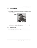
Page 16: ...ge in a probe holder 1 On the side of the fork unscrew the wing screw enough so that you can pull the fork arm away from the probe holder see Figure 1 2 on page 12 Figure 1 2 Pulling the fork arm away...

Page 17: ...ugh to loosen the bar socket see Figure 1 3 on page 13 Figure 1 3 Loosening the bar socket 2 Move the probe holder on the bar to the desired position and screw the wing screw tight enough to hold the...

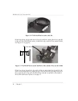
Page 18: ...e encoder holder see Figure 1 5 on page 14 Figure 1 5 The Mini Wheel encoder installed on the outside of the encoder holder When the probes are parallel to the weld and the scanning direction is paral...

Page 19: ...lled on the inside of the encoder holder To install an encoder 1 Use the hexagonal key to loosen the screw securing the Mini Wheel encoder pin into the encoder holder see Figure 1 7 on page 15 Figure...

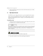
Page 20: ...owing procedure to operate the scanner To operate the scanner 1 Hold the scanner above the inspection surface and then align the scanner so that the inspection area is centered between the probes Depe...

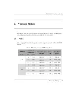
Page 21: ...le 3 on page 17 describes the probes used for inspections made with the HST X04 scanner Table 3 Miniature screw in TOFD transducers Frequency Nominal element size Transducer part numbers Case type Cas...

Page 22: ...rt of the transducer part number indicates that two types of connectors are available SM Microdot connectors or SL LEMO 00 connectors Table 4 Miniature TOFD screw in wedges ST1 wedge type ST2 wedge ty...

Page 23: ...hanical interference ST1 60La ST2 60La 60 ST1 60L IHCb ST2 60L IHCb 60 ST1 60L IHSc 60 ST1 70La ST2 70La 70 ST1 70L IHCb ST2 70L IHCb 70 ST1 70L IHSc 70 a Comes standard with scanner holes b IHC Irrig...

Page 24: ...DMTA020 01EN Rev D September 2016 Chapter 2 20...

Page 25: ...HST X04 does not require preventive maintenance Only a regular inspection of the product is recommended to ensure that the HST X04 scanner functions correctly 3 2 Unit Cleaning The HST X04 scanner ex...

Page 26: ...DMTA020 01EN Rev D September 2016 Chapter 3 22...

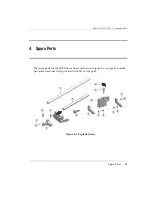
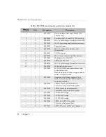
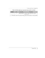
Page 27: ...v D September 2016 Spare Parts 23 4 Spare Parts The spare parts for the HST X04 scanner are shown in Figure 4 1 on page 23 and the part and accessories list is provided in Table 5 on page 24 Figure 4...

Page 28: ...779451 Modified screw 28LA0032 10 2 Q8300906 Sliding probe holder 11 4 U8900318 M5 16 mm hexagonal stainless steel screw 12 2 U8900342 M5 butterfly head screw 1 U8775085 HST X04 TOFD hand scanner fram...

Page 29: ...20 01EN HST X04 Manual Weld TOFD Scanner User s Manual a This number represents the typical quantity initially included with your scanner package Table 5 HST X04 scanner spare part and accessories lis...

Page 30: ...DMTA020 01EN Rev D September 2016 Chapter 4 26...

Page 31: ...lled on the inside of the encoder holder 275 mm 10 8 in with the 250 mm bar and the Mini Wheel encoder installed on the inside of the encoder holder Width 60 mm 2 4 in with the Mini Wheel encoder inst...

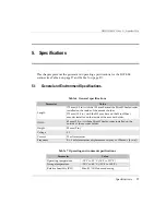
Page 32: ...1 on page 29 contains the pinout for the LEMO connector used on the OmniScan MX2 model Wet location Yes Altitude Up to 2000 m Outdoor use Yes Pollution level 1 IP rating Waterproof designed to meet IP...

Page 33: ...D September 2016 Specifications 29 Figure 5 1 LEMO connector pinout diagram 5 V PHA 1 PHB 1 GND Shield 5 V PHA 1 PHB 1 GND Shield Case Solder cup view Contact view HST X04 Mini Wheel encoder HST X04 M...

Page 34: ...DMTA020 01EN Rev D September 2016 Chapter 5 30...

Page 35: ...away from the probe holder 12 Figure 1 3 Loosening the bar socket 13 Figure 1 4 The Mini Wheel encoder and cable 14 Figure 1 5 The Mini Wheel encoder installed on the outside of the encoder holder 14...

Page 36: ...DMTA020 01EN Rev D September 2016 List of Figures 32...

Page 37: ...Table 2 Ancillary equipment 4 Table 3 Miniature screw in TOFD transducers 17 Table 4 Miniature TOFD screw in wedges 18 Table 5 HST X04 scanner spare part and accessories list 24 Table 6 General specif...

Page 38: ...DMTA020 01EN Rev D September 2016 List of Tables 34...

Page 39: ...RCM Australia 2 connectors scanner interface pinout 28 couplant between probe and wedge 12 D DANGER signal word 6 description 11 dimensions height 27 length 27 width 27 direct current symbol 2 E EMC d...

Page 40: ...anner operation 16 R rating labels symbols 2 RCM mark 2 repair instrument 5 S safety instrument compatibility 4 misuse of instrument 3 precautions 7 signal words 6 symbols 6 scanner assembling 12 inte...

Page 41: ...DMTA020 01EN Rev D September 2016 Index 37 couplant between probe and 12 installation 12 WEEE directive 9 symbol 2 width 27...

Page 42: ...DMTA020 01EN Rev D September 2016 Index 38...

Reviews: