DMTA031-01EN, Rev. B, October 2014
Chapter 2
20
2.2
Power-Cable Connector—for Models with TRPP 5810
Pulser/Preamplifier
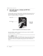
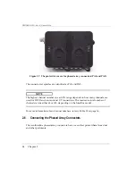
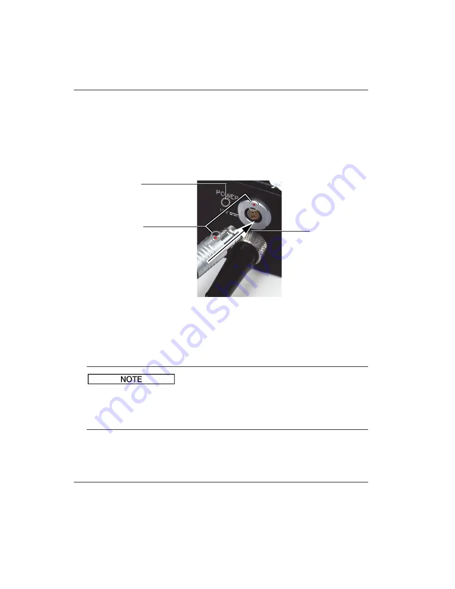
The power-cable connector is marked with a red dot that must be aligned with a red
dot on the connector receptacle on the InterBox before the connection is made (see
Figure 2-2 on page 20 and Figure 2-3 on page 21).
Figure 2-2 Aligning the marks for the power connector
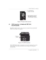
Once the InterBox is correctly connected to an electric power source, the red LED
illuminates (see Figure 2-3 on page 21).
All InterBox models equipped with TRPP 5810 come with two power cables. The first
power cable allows the InterBox to be powered by an OmniScan acquisition unit. The
second power cable allows the InterBox to be powered by a 120 VAC to 240 VAC
source.
Align the two red
dots.
Push the cable
connector into
the receptacle.
Red power LED
Summary of Contents for InterBox EIB-T-8-M-15-OM
Page 6: ...DMTA031 01EN Rev B October 2014 List of Abbreviations vi ...
Page 10: ...DMTA031 01EN Rev B October 2014 Labels and Symbols 4 ...
Page 20: ...DMTA031 01EN Rev B October 2014 Important Information Please Read Before Use 14 ...
Page 22: ...DMTA031 01EN Rev B October 2014 Introduction 16 ...
Page 36: ...DMTA031 01EN Rev B October 2014 Chapter 3 30 ...
Page 44: ...DMTA031 01EN Rev B October 2014 List of Figures 38 ...
Page 46: ...DMTA031 01EN Rev B October 2014 List of Tables 40 ...

