DMTA031-01EN, Rev. B, October 2014
Chapter 2
22
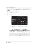
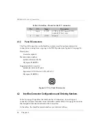
The label on the InterBox face opposing the TOFD connectors provides the connection
information for the integrated TRPP 5810 pulser/preamplifier (see Figure 2-5 on
page 22):
•
P1 and P2 identify the pulser outputs
•
R1 and R2 identify the receiver inputs
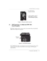
These codes, as well as the channel numbers, are marked next to each connector (see
Figure 2-4 on page 21).
Figure 2-5 The label with probe-connection diagram
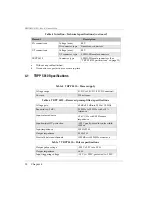
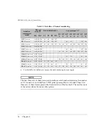
Table 3 InterBox—Pinout for the P and R connectors
Connector
I/O
Description
P1 OUT and P2 OUT
Output
These P connectors are used to
transmit the signals to two
conventional probes.
R1 IN and R2 IN
Input
These R connectors are used to receive
the signals from two conventional
probes.
Summary of Contents for InterBox EIB-T-8-M-15-OM
Page 6: ...DMTA031 01EN Rev B October 2014 List of Abbreviations vi ...
Page 10: ...DMTA031 01EN Rev B October 2014 Labels and Symbols 4 ...
Page 20: ...DMTA031 01EN Rev B October 2014 Important Information Please Read Before Use 14 ...
Page 22: ...DMTA031 01EN Rev B October 2014 Introduction 16 ...
Page 36: ...DMTA031 01EN Rev B October 2014 Chapter 3 30 ...
Page 44: ...DMTA031 01EN Rev B October 2014 List of Figures 38 ...
Page 46: ...DMTA031 01EN Rev B October 2014 List of Tables 40 ...

