19
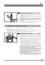
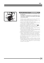
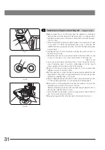
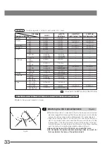
Fig. 18
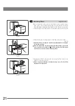
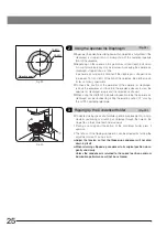
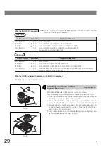
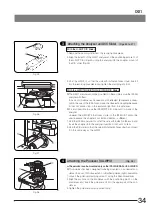
Fig. 19
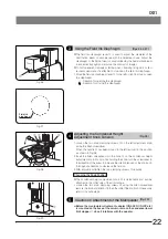
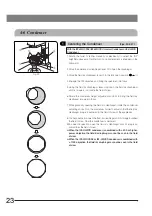
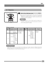
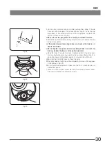
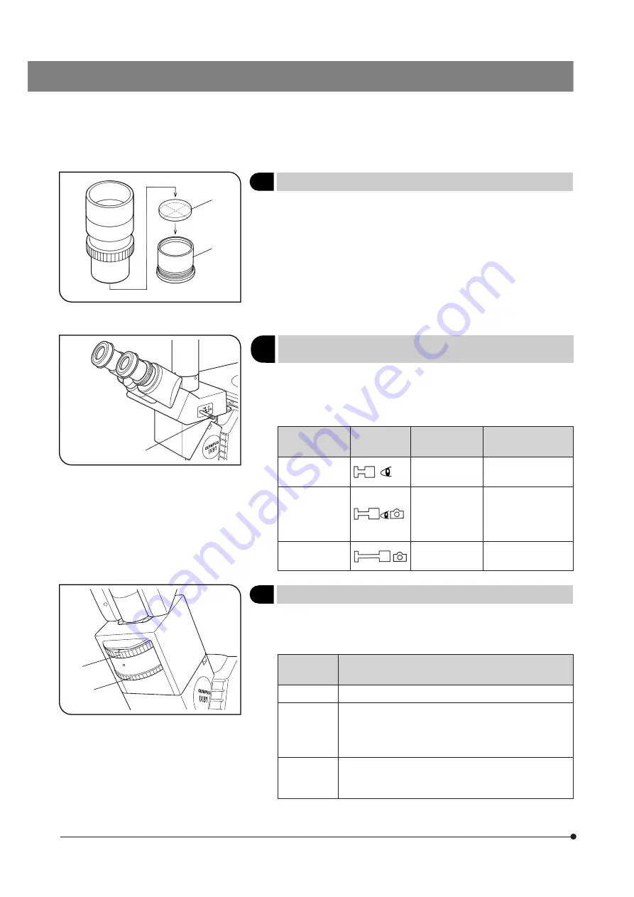
Fig. 20
4
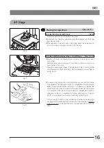
Using Eyepiece Micrometer Disks
(Fig. 18)
Eyepiece micrometer disks can be inserted into the WHN10X-H
(or WHN10X) eyepieces.
Use 24 mm dia. x 1.5 mm micrometer disks.
Following Fig. 18, turn the built-in micrometer mounting frame ² counter-
clockwise to remove it from the eyepiece and place a micrometer disk @
into the mounting frame so that the surface with the model indication
faces downward.
Re-attach the micrometer mounting frame in the original position.
5
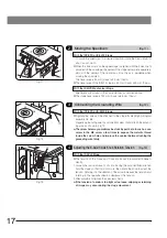
(Fig. 19)
Slide the light path selector knob
1
to select the desired light path.
}Usually, set the selector knob to the intermediate position. With dark speci-
mens, push the knob in. If additional light is needed for TV observation or
photomicrography, pull the knob out.
Light Path
Selector Position
Symbol
Light Path Ratio
Application
Pushed in
Binocular 100%
Observation of dark
specimens
Intermediate
Binocular 20%
TV/photo 80%
Observation of
bright specimens,
photomicrography,
TV observation
Pulled out
TV/photo 100%
Photomicrography,
TV observation
6
Using the CT Turret (U-BI90CT Only)
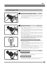
(Fig. 20)
1. To use the CT turret
1
, rotate the knurled ring with a finger to select the
setting corresponding to the indication (0-CT-0-S). (Set the magnification
selector knob on the IX81 microscope frame to 1X.)
Turret
Indication
Application
0 (2 positions)
Nothing is engaged in the light path (Normal observation)
CT
The CT (Centering Telescope) lens is engaged in the light
path and the objective exit pupil can be observed.
Used when centering the ring slit in phase contrast ob-
servation or adjusting the aperture iris diaphragm.
S
Shield plate is engaged in the light path to block extraneous
light from entering through the eyepieces. Used in photomicro-
graphy to prevent extraneous light from affecting the exposure.
2. To bring the exit pupil image of the objective into focus when using the
CT lens, rotate the focusing ring
2
to adjust.
1
2
1
1
2
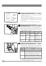
Selecting the Light Path of Observation
Tube (U-TR30H-2 Only)


