IX81
CONTENTS
6
7-10
11-12
13-27
IMPORTANT
— Be sure to read this section for safe use of the equipment. —
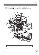
1 MODULE NOMENCLATURE
2 CONTROLS
3
4 USING THE CONTROLS
TRANSMITTED LIGHT BRIGHTFIELD OBSERVATION PROCEDURE
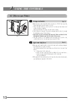
4-1 Microscope Frame
..................................................................................................................................................................
13-14
4-2 Focusing Block
......................................................................................................................................................................................
15
4-3 Stage
............................................................................................................................................................................................................
16-17
4-4 Observation Tube
.....................................................................................................................................................................
18-20
1-5
Correct assembly and adjustments are critical for the microscope to exhibit its full performance. If you are going to
assemble the microscope yourself, please read Chapter 9, “ASSEMBLY” (pages 49 to 58) carefully. For the modules
provided with instruction manuals, also read the assembly procedures in their instruction manuals.
When the IX81 motorized revolving nosepiece is rotated in stand-alone mode (without a PC), automatic es-
cape movement of an objective (prevention of interference between the objective and stage) is not performed.
Therefore, when using an objective with a short working distance, let the motorized revolving nosepiece
escape once before pressing the objective switching button.
1
Voltage Indication
2
Light Path Selection
3
Magnification Change
4
Motorized Revolving Nosepiece
5
Frame Clamping Plate
1
Adjusting the Interpupillary Distance
2
Adjusting the Diopter
3
Using the Eye Shades
4
Using Eyepiece Micrometer Disks
5
Selecting the Light Path of Observation Tube (U-TR30H Only)
6
Using the CT Turret (U-BI90CT Only)
7
Adjusting the Tilt (U-TBI90 Only)
1
Placing the Specimen
2
Moving the Specimen
3
Connecting the Grounding Wire
4
Adjusting the X-Axis/Y-Axis Knob Rotation Tension
1
Rotation Direction of the Focusing Knob
2
Coarse/Fine Adjustment Switching Button
3
Focusing (UP/DOWN) buttons
4
Objective Escape/Return (ESC) Button
Note on operation in stand-alone mode
4-5 Illumination Column (IX2-ILL100)
......................................................................................................................
20-22
1
Tilting the Illumination Column
2
Mounting Filters
3
Using the Field Iris Diaphragm
4
Adjusting the Condenser Height Adjustment Knob Tension
5
Caution on Attachment of the Manipulator


