104
Chapter 5 Operation
VIDEO SYSTEM OTV-SI
•
The number of switches displayed (see Figure 5.60) depends
upon the number of remote control switches on the
videoscope or camera head.
•
Depending upon the instrument settings, the menu shown in
Figure 5.60 may differe from that displayed on the video
monitor.
8.
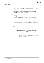
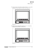
Press the remote control switch for selection, the “
” or “
” key on the
keyboard and select the switch number to be assigned (for example,
“SW1”).
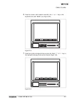
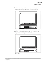
9.
Press the remote control switch for execution, the “Enter”, “
” or “
” key
on the keyboard to select the function to assign to the switch (for example,
“FREEZ”) (see Figure 5.61).
Figure 5.61
VISY218
Summary of Contents for OTV-SI
Page 2: ...VISY218...
Page 6: ...Contents iv VIDEO SYSTEM OTV SI VISY218...
Page 148: ...142 Chapter 7 Troubleshooting VIDEO SYSTEM OTV SI VISY218...
Page 156: ...VISY218...
Page 159: ...INSTRUCTIONS COMPACT TROLLEY TC C2 VISY218...
Page 171: ...VISY218...
Page 172: ...VISY218...
Page 173: ...VISY218...

