TC--C2 COMPACT TROLLEY
7
4.7
Four foot holders should be affixed to the second and third shelves in suitable positions for the equipment being used.
4.8
Place items of equipment onto the shelving, ensuring that the equipment feet are located in the foot holders to prevent
equipment from moving.
D
Refer to individual equipment instructions for connection details. Cable restraints are provided on the rear of each
shelf.
D
The TC--C2 has been designed to allow use of the Olympus MB--631 isolation transformer, which should be seated
in the base of the TC--C2 towards the rear.
4.9
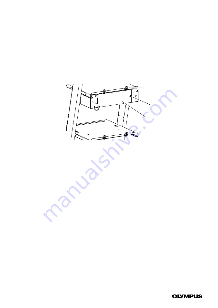
Plugblock versions only:
Using a suitable flat bladed implement, turn the fastener 90
˚
and release the plugblock cover.
Connect equipment power cables to the plugblock ensuring they exit from the base allowing the cover to be closed. Tidy
excess lengths of cable using the cable straps on the rear of the workstation. Replace the cover and lock the fastener.
Cable straps
Plugblock cover
Fastener
FIGURE 4-5
Connection information
When assembling equipment onto the workstation, the installation should meet the requirements of EN IEC 60601--1--1,
the safety standard for medical electrical systems.
This standard requires the aggregate earth leakage current of items powered via a plugblock to be less than 0.5mA.
This may be achieved by limited use of the plugblock or the use of an isolation transformer.
Before commissioning an installation where an isolation transformer is included, ensure its rating will not be exceeded
by the equipment connected to it.
The plugblock is provided with a cover to prevent connection of equipment that may cause the earth leakage current to
exceed IEC limits.
The plugblock must not be placed on the floor when in use.
The maximum permitted load on the plugblock is 15 amps in USA and 13 amps in Europe.
The plugblock must only be used to power equipment which forms part of the System.
Equipment powered through an Isolation Transformer must not be connected to equipment not meeting the leakage
current requirements of EN IEC 60601--1 which is connected directly to the wall socket as this may compromise system
safety.
The connection of equipment to the plugblock subsequent to the initial system installation must be undertaken by
suitably qualified personnel in order to minimise the risk of system safety being compromised by excessive leakage
currents.
VISY218
Summary of Contents for OTV-SI
Page 2: ...VISY218...
Page 6: ...Contents iv VIDEO SYSTEM OTV SI VISY218...
Page 148: ...142 Chapter 7 Troubleshooting VIDEO SYSTEM OTV SI VISY218...
Page 156: ...VISY218...
Page 159: ...INSTRUCTIONS COMPACT TROLLEY TC C2 VISY218...
Page 171: ...VISY218...
Page 172: ...VISY218...
Page 173: ...VISY218...

