Chapter 2 Nomenclature and Functions
15
VIDEO SYSTEM OTV-SI
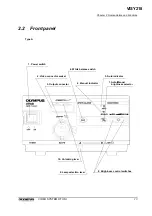
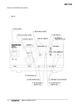
1. Power switch
This switch is pressed to turn the video system ON or OFF.
2. Video connector socket
The video plug of the videoscope or camera head is connected to this
socket.
3. Output connector
The connector transmits light to the connected videoscope or light guide
cable.
4. White balance switch
This switch is pressed to automatically adjust the white balance.
5. Auto indicator
This indicator lights when the auto brightness control is selected.
6. Manual indicator
This indicator lights when the manual brightness control is selected.
7. Auto/Manual brightness selector
This switch is pressed to select auto or manual brightness control.
8. Brightness control switches
These switches are pressed to set the video brightness level (in auto mode),
or to adjust the light level (in manual mode).
9. Lamp selection lever
The lamp selection lever is moved to change the lamp.
10. Unlocking lever
This lever is pushed down to disconnect the video plug of the videoscope or
camera head.
11. Air feed switch (type B only)
This switch is pressed to start or stop air feeding.
12. Air feed indicator (type B only)
This indicator lights when air is feeding.
VISY218
Summary of Contents for OTV-SI
Page 2: ...VISY218...
Page 6: ...Contents iv VIDEO SYSTEM OTV SI VISY218...
Page 148: ...142 Chapter 7 Troubleshooting VIDEO SYSTEM OTV SI VISY218...
Page 156: ...VISY218...
Page 159: ...INSTRUCTIONS COMPACT TROLLEY TC C2 VISY218...
Page 171: ...VISY218...
Page 172: ...VISY218...
Page 173: ...VISY218...

