background image

DMTA041-01EN [U8778479], Rev. C, May 2014

System Installation


25

2. System Installation

This chapter explains the procedures for installing the TomoScan FOCUS LT and for 
connecting the system components and peripherals to the main instrument.

2.1

Standard Equipment

The packing list should include the following items:

TomoScan FOCUS LT with the proper internal configuration

AC power cord

Crossover Ethernet cable (category 5e or higher)

USB drive including the TomoView installation software, TomoView user’s 
manual, and TomoScan FOCUS LT user’s manual

Calibration certificate

Probe adaptor (optional item)

2.2

Instrument Installation

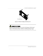
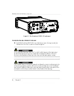
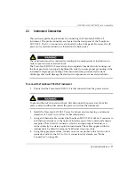
This section provides installation instructions for the TomoScan FOCUS LT (see 
Figure 2-1 on page 26).

Summary of Contents for TomoScan FOCUS LT

Page 1: ...ument User s Manual This instruction manual contains essential information on how to use this Olympus product safely and effectively Before using this product thoroughly review this instruction manual...

Page 2: ...the accuracy of the information contained therein and corresponds to the version of the product manufactured prior to the date appearing on the title page There could however be some differences betw...

Page 3: ...ruction Manual 5 Instrument Compatibility 5 Repair and Modification 6 Safety Symbols 6 Safety Signal Words 7 Note Signal Words 7 Safety 8 Warnings 8 Battery Precautions 9 Equipment Disposal 10 WEEE Di...

Page 4: ...Fan Filters 36 4 3 1 Cleaning the Fan Filters 37 4 3 2 Changing the Fan Filters 37 4 4 Fuse Changing 38 4 5 Troubleshooting 40 5 Specifications 41 5 1 General Specifications 41 5 2 Operating Specific...

Page 5: ...TA041 01EN U8778479 Rev C May 2014 Table of Contents v 6 3 DC IN Connector 63 6 4 ETHERNET Connector 64 6 5 P Connectors 65 6 6 UT PHASED ARRAY Connector 66 List of Figures 67 List of Tables 69 Index...

Page 6: ...DMTA041 01EN U8778479 Rev C May 2014 Table of Contents vi...

Page 7: ...y related labels and symbols are attached to the instrument at the locations shown in Figure i 1 on page 1 If any or all of the labels or symbols are missing or illegible please contact Olympus Figure...

Page 8: ...pean Community See the Declaration of Conformity for details Contact your Olympus representative for more information The WEEE symbol indicates that the product must not be disposed of as unsorted mun...

Page 9: ...nnectors shown in the figure below warns of this electric shock risk SERIAL The serial number is a nine 9 digit number in the following format yynnnddmm where yy Production year nnn Unit number manufa...

Page 10: ...DMTA041 01EN U8778479 Rev C May 2014 Labels and Symbols 4...

Page 11: ...ended use It must never be used to inspect or examine human or animal body parts Instruction Manual This instruction manual contains essential information on how to use this Olympus product safely and...

Page 12: ...human injury and or equipment damage do not disassemble modify or attempt to repair the instrument Safety Symbols The following safety symbols might appear on the instrument and in the instruction ma...

Page 13: ...performed or adhered to could result in death or serious personal injury Do not proceed beyond a WARNING signal word until the indicated conditions are fully understood and met The CAUTION signal word...

Page 14: ...gory II Before turning on the instrument verify that the correct safety precautions have been taken see the following warnings In addition note the external markings on the instrument which are descri...

Page 15: ...or short circuited fuse holders doing so could cause electric shock or create a fire hazard If there is any possibility that the ground protection could be impaired you must make the instrument inope...

Page 16: ...accordance with the manufacturer s instructions may cause interference The TomoScan FOCUS LT has been tested and found to comply with the limits for an industrial device in accordance with the specif...

Page 17: ...s intended solely as a teaching aid and shall not be used in any particular application without independent testing and or verification by the operator or the supervisor Such independent verification...

Page 18: ...DMTA041 01EN U8778479 Rev C May 2014 Important Information Please Read Before Use 12...

Page 19: ...lel Key Features TomoScan FOCUS LT instrument s key features include 16 32 or 64 focusing channels Up to 128 channels with linear amplifier for phased array inspection Real time data compression High...

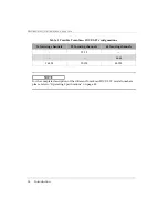
Page 20: ...plete description of the different TomoScan FOCUS LT model numbers please refer to Operating Specifications on page 42 Table 2 Possible TomoScan FOCUS LT configurations 16 focusing channels 32 focusin...

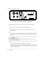
Page 21: ...les the user to perform the following Connect a phased array probe to the TomoScan FOCUS LT Connect up to 4 conventional ultrasound probes Enable or disable UT conventional ultrasound mode Connect the...

Page 22: ...N This connector allows the TomoScan FOCUS LT to be supplied from a DC power source The DC IN connector accepts voltages in the range of 15 VDC to 24 VDC rated at 5 A The external DC power supply must...

Page 23: ...l ultrasound mode with the P125 P126 P127 and P128 connectors the voltage present on the P connectors can be dangerous and create a shock hazard AC The letters AC stand for alternating current When th...

Page 24: ...econd it indicates that the unit is starting up When this indicator turns off after blinking it indicates that the unit is ready for operation ETHERNET This 8 position modular connector enables the co...

Page 25: ...the AC source first disconnect the power cord from the AC outlet and then disconnect the power cord from the back of the instrument Failure to do so can cause electric shocks Handles Two handles are...

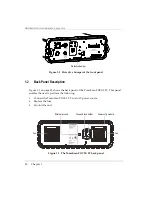
Page 26: ...ure 1 3 on page 20 shows the back panel of the TomoScan FOCUS LT This panel enables the user to perform the following Connect the TomoScan FOCUS LT to an AC power source Replace the fuse Ground the un...

Page 27: ...power source The DC IN connector located on the front panel accepts voltages between 15 VDC and 24 VDC rated at 5 A POWER CORD PROVIDES AC POWER DISCONNECT This marking on the back panel indicates tha...

Page 28: ...nspection Fans Two fans cool the internal components Each fan has a mesh filter used to filter air drawn in by the fan Two grills for the air outlet are located on both sides of the TomoScan FOCUS LT...

Page 29: ...bumpers of the back panel Do not leave the TomoScan FOCUS LT vertical on the bumpers of the back panel because the high center of gravity could make it unstable and likely to fall over Moreover the i...

Page 30: ...DMTA041 01EN U8778479 Rev C May 2014 Chapter 1 24...

Page 31: ...e packing list should include the following items TomoScan FOCUS LT with the proper internal configuration AC power cord Crossover Ethernet cable category 5e or higher USB drive including the TomoView...

Page 32: ...e bumpers of the back panel because the high center of gravity could make it unstable and likely to fall over Moreover the insufficient clearance of the fans would impede proper cooling The TomoScan F...

Page 33: ...c components or cause electric shocks To connect the TomoScan FOCUS LT instrument 1 Ensure that the TomoScan FOCUS LT is disconnected from the power source To prevent the risk of an electric shock fir...

Page 34: ...ower outlet Turn on the TomoScan FOCUS LT by pressing the front panel on off switch 7 When using a DC power source connect the power cord to the DC IN connector of the TomoScan FOCUS LT front panel Co...

Page 35: ...emotely turn on a TomoScan FOCUS LT from an AC power source When this mode is enabled you do not need to press the front panel on off switch to start the TomoScan FOCUS LT The instrument starts automa...

Page 36: ...h on the front panel 3 Reconnect the DC power cord to the DC IN input connector or turn on the external DC power source 4 Release the on off switch on the front panel when the STBY indicator light is...

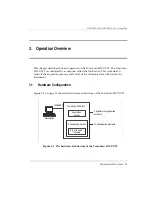
Page 37: ...ation controls the acquisition process and analyzes the ultrasonic data collected by the instrument 3 1 Hardware Configuration Figure 3 1 on page 31 shows the hardware architecture of the TomoScan FOC...

Page 38: ...in order to produce data UT I O The phased array section manages the focal laws transmission delay reception delay signal summing The RPC server is used for the configuration of the focal laws 3 3 Wo...

Page 39: ...FOCUS LT is designed to be used with a 100BASE T Fast Ethernet network The TomoScan FOCUS LT has no internal disk drive The instrument must therefore be linked through an Ethernet network to a worksta...

Page 40: ...DMTA041 01EN U8778479 Rev C May 2014 Chapter 3 34...

Page 41: ...preventive maintenance Only a regular inspection of the instrument is recommended to ensure that the TomoScan FOCUS LT has adequate grounding The TomoScan FOCUS LT must always be completely inserted...

Page 42: ...he connector contacts could stay wet and produce a short circuit when connecting cables 3 To remove persistent stains use a damp cloth with a soft soapy solution Do not use abrasive products or powerf...

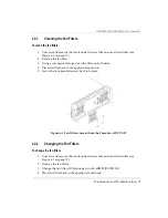
Page 43: ...lean the filter on both sides 4 Place the filter back in the appropriate position 5 Screw the four knurled screws back into place Figure 4 1 Fan filter removed from the TomoScan FOCUS LT 4 3 2 Changin...

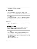
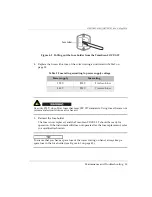
Page 44: ...qualified technician for replacement To change the fuse 1 Ensure that the instrument is turned off and the AC power cord is disconnected from the back panel of the instrument To prevent the risk of an...

Page 45: ...ded could cause a fire hazard 5 Reinsert the fuse holder The fuse is now replaced and the TomoScan FOCUS LT should be ready for operation If the instrument still does not operate after the fuse replac...

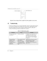
Page 46: ...ded and suggested by Olympus Table 4 Troubleshooting guide Problem Cause Solution The instrument does not turn on The fuse is blown Verify the fuse and replace it if applicable with a fuse of the corr...

Page 47: ...ifications Category Specification Value Housing Size W H D 31 3 cm 11 4 cm 37 7 cm 12 32 in 4 49 in 14 83 in Net weight 5 kg 11 lb Environment Storage temperature 20 C to 60 C Operating temperature In...

Page 48: ...up 5 2 Operating Specifications This section details the operating specifications of the TomoScan FOCUS LT 5 2 1 Pulser Receiver Differences and Limitations The pulser receiver specifications are give...

Page 49: ...higher voltage in the load compared to models R Models with the letter R For law in pitch and catch mode Number of pulsing channels Maximum active channels Number of receiving channels Maximum active...

Page 50: ...FLT16128 P O K 1 K L Pulse echo N 15 M 15 K 1 K L Pitch and catch N 7 M 7 Limit 4 K L M 16 n 1 2 3 4 5 6 7 FLT16128 R O K 1 K L Pulse echo N 15 M 15 K 1 K L Pitch and catch N 15 M 15 FLT32128 P O K 1...

Page 51: ...1 FLT64128 R O K 1 K L Pulse echo N 63 M 63 K 1 K L Pitch and catch N 63 M 63 FLT6464 P O K 1 K L Pulse echo N 63 M 63 K 1 K L Pitch and catch N 31 M 31 Table 7 Specifications of models FLT16128 P O...

Page 52: ...frequency at 3 dB Overall system bandwidth in pitch and catch 0 54 MHz 10 to 20 MHz 12 cuto frequency at 3 dB Filters All filters are 10 cuto frequency at 3 dB 0 4 MHz to 1 7 MHz band pass 1 1 MHz to...

Page 53: ...s steps of 2 5 ns Dynamic depth focusing DDF Yes Table 8 Specifications of models FLT32128 P O and FLT32128 R O Category Specification FLT32128 P O FLT32128 R O Pulser Pulse voltage 40 V 80 V and 115...

Page 54: ...andwidth 0 54 MHz 10 to 22 MHz 12 cuto frequency at 3 dB Filters All filters are 10 cuto frequency at 3 dB 0 4 MHz to 1 7 MHz band pass 1 1 MHz to 3 4 MHz band pass 2 0 MHz to 7 4 MHz band pass 3 3 MH...

Page 55: ...s steps of 2 5 ns Dynamic depth focusing DDF Yes Table 9 Specifications of models FLT64128 P O and FLT64128 R O Category Specification FLT64128 P O FLT64128 R O Pulser Pulse voltage 40 V 80 V and 115...

Page 56: ...ndwidth 0 54 MHz 10 to 23 5 MHz 12 cuto frequency at 3 dB Filters All filters are 10 cuto frequency at 3 dB 0 4 MHz to 1 7 MHz band pass 1 1 MHz to 3 4 MHz band pass 2 0 MHz to 7 4 MHz band pass 3 3 M...

Page 57: ...0 10 s steps of 2 5 ns Dynamic depth focusing DDF Yes Table 10 Specifications of models FLT3232 P O and FLT6464 P O Category Specification FLT3232 P O FLT6464 P O Pulser Pulse voltage 50 V 100 V and 2...

Page 58: ...3 4 MHz band pass 2 0 MHz to 7 4 MHz band pass 3 3 MHz to 7 5 MHz band pass 4 4 MHz to 11 MHz band pass 5 5 MHz to 15 MHz band pass 6 3 MHz to 20 MHz band pass 9 7 MHz to 22 MHz band pass 4 1 MHz to...

Page 59: ...ond to the last four channels of the UT PHASED ARRAY connector The specifications for these channels are the same ones as the specifications for the phased array channels When the instrument is used i...

Page 60: ...external signal Synchronization modes Pulser surface echo external trigger A scan recording Up to 8000 A scans s 512 samples of 8 bits C scan data Up to 20 kHz four measurement gates plus synchronizat...

Page 61: ...quadrature clock directions up down Digital input 2 digital inputs for more information see I O Connector on page 60 Digital output 4 digital outputs for more information see I O Connector on page 60...

Page 62: ...with the essential requirements of the applicable directives of the European Union that is the Low Voltage Directive 2006 95 EC and the EMC Directive 2004 108 EC The conformity has been assessed with...

Page 63: ...e FCC Rules These limits are designed to provide reasonable protection against harmful interference when the equipment is operated in a commercial environment This equipment generates uses and can rad...

Page 64: ...DMTA041 01EN U8778479 Rev C May 2014 Chapter 5 58...

Page 65: ...following information a brief description the manufacturer number the number of the corresponding cable connector an illustration and a table giving the specifications or the signal pinouts for the co...

Page 66: ...ure 6 1 The I O connector Table 13 Pinout for the I O connector Pin I O Signal Description Type Signal length A Input PhB 1 Encoder 1 phase B direction TTLa B Output Dout1 Programmable output Configur...

Page 67: ...ut Not programmed in TomoView TTLa P Input PhB 2 Encoder 2 phase B direction TTLa R Input Din2 Programmable input Can be configured as rotation sync input revolution synchronization signal or as prese...

Page 68: ...required DIN signal is greater than 50 s then maximum PRF will be lower than 10 kHz Figure 6 2 The Trig on Dout 2 for a signal of 50R 6 2 DC OUT Connector Description 5 pin female connector Manufactur...

Page 69: ...2 pin male connector Manufacturer number W W Fischer Inc D 103 Z051 60 Olympus 21AB0321 U8902550 Suggested cable connector number W W Fischer Inc S 103 Z051 130 Olympus 21AB0322 U8908014 Table 14 Pin...

Page 70: ...nector Manufacturer number Stewart Connector SS 650810SAFLS Olympus 21AI0080 Suggested cable connector number Stewart Connector 940SP 360808 Olympus 21AI0079 Figure 6 5 The ETHERNET connector Table 15...

Page 71: ...Suggested cable connector number LEMO FFC 00 250 CTAC31 Equivalent W W Fischer Inc S 101 A004 3 0 Olympus 21AB0016 U8907038 Figure 6 6 The P connectors Table 16 Pinout for the ETHERNET connector Pin...

Page 72: ...UT PHASED ARRAY Connector Description 160 pin female Minidock type connector Manufacturer number Global Components 30033 160T Olympus 21AI0170 U8904017 Suggested cable connector number Framatome 89649...

Page 73: ...e architecture of the TomoScan FOCUS LT 31 Figure 4 1 Fan filter removed from the TomoScan FOCUS LT 37 Figure 4 2 Pulling out the fuse holder from the TomoScan FOCUS LT 39 Figure 4 3 Fuse and spare fu...

Page 74: ...DMTA041 01EN U8778479 Rev C May 2014 List of Figures 68...

Page 75: ...s of models FLT16128 P O and FLT16128 R O 45 Table 8 Specifications of models FLT32128 P O and FLT32128 R O 47 Table 9 Specifications of models FLT64128 P O and FLT64128 R O 49 Table 10 Specifications...

Page 76: ...DMTA041 01EN U8778479 Rev C May 2014 List of Tables 70...

Page 77: ...8 P O 51 FLT64128 R O 51 FLT6464 P O 52 Bootp server 33 bumpers protective 19 22 button UT ON 16 C cable part number crossover 33 Canadian and U S standards 56 CAUTION signal word 7 cautions See also...

Page 78: ...EMC 56 disposal equipment 10 E electric shock danger note 3 EMC directive 56 EMC directive compliance 10 environment specifications 41 equipment disposal 10 Ethernet cable 55 56 connector 18 64 65 li...

Page 79: ...36 compatibility 5 connecting 27 description 13 overview 15 back panel 20 front panel 15 positioning warning 23 26 K key features 13 L labels 1 LEDs See indicator lights LEMO 01 connectors 3 link Ethe...

Page 80: ...supply warning 19 21 precautions battery 9 preventive maintenance 35 probes connecting 28 caution 28 protective bumpers 19 22 pulser receiver specifications 42 FLT16128 P O 45 FLT16128 R O 45 FLT32128...

Page 81: ...uipment 25 system specifications 41 T TCG specifications 54 technical support 11 terminal ground 22 Time Corrected Gain specifications 54 TIP signal word 8 troubleshooting 40 changing the fuse 38 U U...

Page 82: ...DMTA041 01EN U8778479 Rev C May 2014 Index 76...

Reviews: