DMTA041-01EN [U8778479], Rev. C, May 2014
System Installation
27
2.3
Instrument Connection
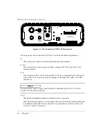
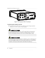
This section explains the procedure for connecting the TomoScan FOCUS LT
instrument. The probe connectors are located on the front panel of the TomoScan
FOCUS LT. The
DC IN
connector is also located on the front panel. However, the AC
power entry module connector is located on the back panel.
The instrument must be connected according to the manufacturer’s instructions in
order to prevent risk of electric shock.
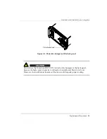
The TomoScan FOCUS LT must always be completely inserted into its housing and
the front panel screws properly tightened in order to ensure proper grounding of the
instrument. Improper grounding of the instrument may produce electrostatic
discharges that could damage the electronic components or cause electric shocks.
To connect the TomoScan FOCUS LT instrument
1.
Ensure that the TomoScan FOCUS LT is disconnected from the power source.
To prevent the risk of an electric shock, first disconnect the power cord from the
power outlet, and then disconnect the power cord from the instrument.
2.
Install the TomoScan FOCUS LT away from heat sources, leaving a minimum
clearance of 5 cm (2 in.) to allow for heat dissipation.
3.
Using an Ethernet cable, connect the TomoScan FOCUS LT
ETHERNET
connector to
an Ethernet network or to the network interface card of the control and analysis
computer. The
ETHERNET
connector, which is an input/output terminal, can
connect directly to a data-acquisition instrument. The cable supplied with the
instrument is by default a category 5e Ethernet crossover cable.
4.
Using the appropriate cables, connect one or more probes to the
PHASED
ARRAY
connector and/or to the
P125
to
P128
UT
connectors (for details, see “Probe
Summary of Contents for TomoScan FOCUS LT
Page 6: ...DMTA041 01EN U8778479 Rev C May 2014 Table of Contents vi...
Page 10: ...DMTA041 01EN U8778479 Rev C May 2014 Labels and Symbols 4...
Page 18: ...DMTA041 01EN U8778479 Rev C May 2014 Important Information Please Read Before Use 12...
Page 30: ...DMTA041 01EN U8778479 Rev C May 2014 Chapter 1 24...
Page 40: ...DMTA041 01EN U8778479 Rev C May 2014 Chapter 3 34...
Page 64: ...DMTA041 01EN U8778479 Rev C May 2014 Chapter 5 58...
Page 74: ...DMTA041 01EN U8778479 Rev C May 2014 List of Figures 68...
Page 76: ...DMTA041 01EN U8778479 Rev C May 2014 List of Tables 70...
Page 82: ...DMTA041 01EN U8778479 Rev C May 2014 Index 76...

