background image

U-FWT/FWR/FWO

6

2

    Mounting the Filter Wheel on the Microscope

(Figs. 3 - 5)

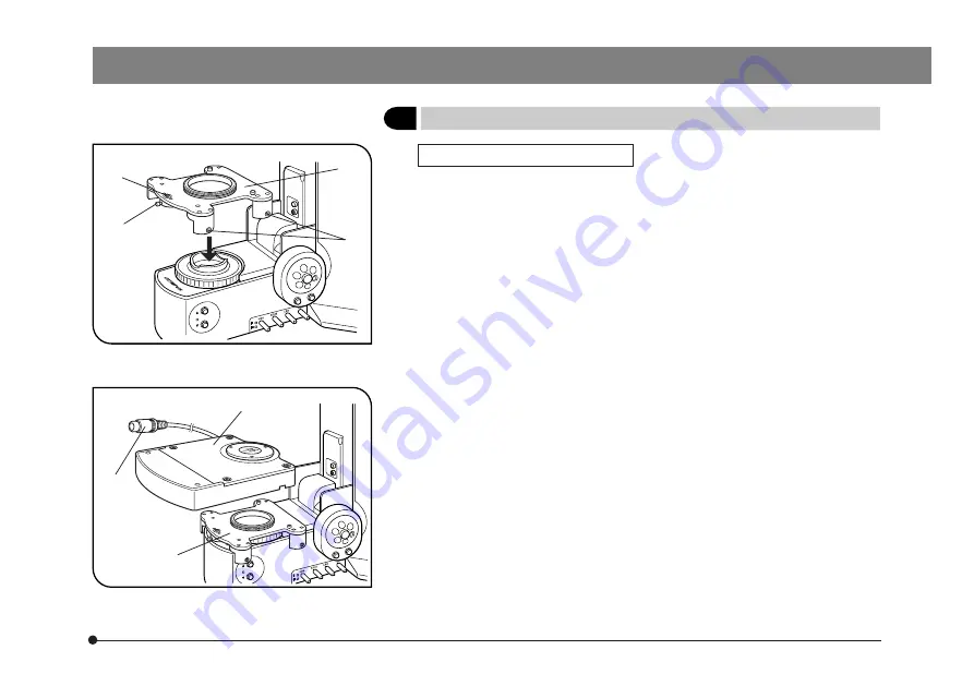
U-FWT Filter Wheel (Figs. 3 & 4)

}The U-FWT can be mounted only to a BX2 series microscope (BX41/51/

52/61/62 microscope frame compatible with reflected light illmination).

1. Loosen the clamping screw ² of the lift prevention pin @ using the Allen

screwdriver.

2. Loosen the 4 clamping screws ³ on each side using the Allen screw-

driver.

3. Fit the filter wheel mount | on the filter holder on the BX2 series micro-

scope.

4. While pushing down the filter wheel mount, tighten the clamping screws

³ uniformly so that the filter wheel mount is parallel with the microscope
base.

5. While pushing down the lift prevention pin @, tighten the clamping screw

².

6. Fit the filter wheel ƒ on the filter wheel mount |. During this, place the

connection cable … in the cable groove on the back side of the filter
wheel ƒ.

7. Tighten the clamping screws on the left side panel of the filter wheel using

the Allen screwdriver.

8. Connect the connection cable … of filter wheel to one of connectors FW1,

2 and 3 on the BX-UCB.

Fig. 3

Fig. 4

@

²

³

|

|

ƒ

Summary of Contents for U-FWO

Page 1: ...ted Light Reflected Light Observation Filter Wheels To ensure the safety obtain optimum performance and to familiarize yourself fully with the use of this unit we recommend that you study this manual thoroughly before operating the unit Retain this instruction manual in an easily accessible place near the work desk for future reference Optical Microscope Accessory ...

Page 2: ... Refer to your local Olympus distributor in EU for return and or collection systems available in your country For Korea only ࣾ匏ࣜ匶匶ࣜࣜࣤ儆洛殯ࣜ愯暧皻柦匶沖沲ࣥ 決ࣜ匶匶垚ࣜ儆洛殯ࣤࣾ匏ࣥࣜ洊沖砒洇穯匶匶嵢昢ࣜ渂嵢ࣜ儆洛櫖昢ࣜ斲殯穞垚ࣜ冉汊 徯洇求嵢ࣜ穞彶ࣨࣜ微姦ࣜ滆櫳櫖昢ࣜ斲殯穦ࣜ朞ࣜ沎枻城埪 This product is a part of the system product which complies with the CE marking Please refer to the instruction manual of your system product for the safety instructions related to the C...

Page 3: ...oscope U FWT FWR FWO CONTENTS If you have not completed filter mounting and its installation on the microscope refer to Chapter 3 ASSEMBLY pages 4 to 8 first IMPORTANT Be sure to read this chapter for safe use of the equipment 1 2 1 SYSTEM DIAGRAM 3 2 VARIOUS MICROSCOPY PROCEDURES 4 3 ASSEMBLY 4 8 ...

Page 4: ...the position where it is attached by magnetism in advance to prevent it from dropping If the driver drops in a certain place an electric shock and or bums may result 1 Getting Ready 1 A filter wheel is a precision instrument Handle it with care and avoid subjecting it to sudden or severe impact and connect cables gently 2 Do not use the filter wheel where it is subjected to direct sunlight high te...

Page 5: ...instruction manual The following symbols are used to set off text in this instruction manual Indicates that failure to follow the instructions in the warning could result in bodily harm to the user and or damage to equipment including objects in the vicinity of the equipment Indicates that failure to follow the instructions could result in damage to equipment Indicates commentary for ease of opera...

Page 6: ...FWR U FWR x 2 stages U FWO BX2 series OK OK OK OK BX series No OK OK OK AX series No OK No OK Note IX IX2 series No OK OK OK Connect to one of FW1 2 and 3 of the BX UCB Transmitted Light Filter Wheel U FWT Connect to one of FW1 2 and 3 of the BX UCB Microscope Reflected Light Filter Wheel U FWR Connect to one of FW1 2 and 3 of the BX UCB Control Box BX UCB Hand Switch U HSTR2 Note Cannot be mounte...

Page 7: ...on 1 Inserting the Filters in the Filter Wheel Figs 1 2 With the U FWT the function of the U UCD8A motorized condenser can be extended by attaching the U FWCO1 25X low magnification correction lens and U FW32PO polarizer in addition to the filter wheel 1 Loosen the 4 filter wheel cover clamping screws using the Allen screw driver provided with the microscope then remove the cover Filters with up t...

Page 8: ...ver which is attached by magnetic absorp tion to the filter wheel into the slit on the push ring insert the ring clockwise the clamp the filter When attaching a 25 mm filter on a conversion adapter use the smaller blade of the ring driver To prevent flare the filter insertion section of conversion adapters is tilted by 5 Take care of the tilting when attaching a filter Barrier filters and excitati...

Page 9: ...e filter holder on the BX2 series micro scope 4 While pushing down the filter wheel mount tighten the clamping screws uniformly so that the filter wheel mount is parallel with the microscope base 5 While pushing down the lift prevention pin tighten the clamping screw 6 Fit the filter wheel ƒ on the filter wheel mount During this place the connection cable in the cable groove on the back side of th...

Page 10: ... in super widefield observation FN26 5 This is barely noticeable with FN22 Heat Caution Since the U FWR is mounted near the lamp housing its surface be comes extremely hot You may accidentally touch the U FWR when operating the collector lens focusing knob of the lamp housing So we recommend that you use the U CLA optional extension knob 1 Attach the lamp housing on the filter wheel This is becaus...

Page 11: ...IX ATU insufficient light amount may be noticeable with FN22 in the peripheral area 1 Fit the circular dovetail on the bottom of the filter wheel in the mount on the observation tube mount then tighten the observation tube clamping screw using an Allen screwdriver If the filter wheel interferes with the projected part of the motor rotate the filter wheel as required 2 Attach the observation tube o...

Page 12: ...geunsa ro Gangnam gu Seoul 06153 Korea Distributed by Manufactured by 48 Woerd Avenue Waltham MA 02453 U S A Shinjuku Monolith 2 3 1 Nishi Shinjuku Shinjuku ku Tokyo 163 0914 Japan www olympus global com Printed in Japan 20160229 M0000 ...

Reviews: