background image

2

U-UVF248A

SAFETY PRECAUTIONS

  Safety Symbols

The following symbols are found on the unit. Study the meaning of the symbols and always use the equipment in the
safest possible manner.

l

Explanation

A high voltage (1 kV or more) is present. Be careful against electric shock.

Symbol

Indicates that the surface becomes hot, and should not be touched with bare hands.

Before use, carefully read the instruction manual. Improper handling could result in injury to
the user and/or damage to the equipment.

Indicates that the main switch is ON.

Indicates that the main switch is OFF.

1. This unit is a precision instrument. Handle it with care and avoid subjecting it to sudden or severe impacts.
2. The mercury/xenon burner should be the UXM80E (USHIO), which is available through Olympus.
3. Before using the unit, ensure that the burner is mounted and that cords are connected properly.
4. The lamp housing becomes very hot during and right after use. Do not open the lamp housing during these periods.
5. When the hour counter on the power supply indicates 1000 hours, set the main switch to “    ” (OFF), wait for more than

10 minutes and then replace the burner. Unlike a fluorescent lamp, the mercury/xenon burner seals high-pressure gas
inside. If it is used extremely beyond the service life, accumulated distortion of the glass tube could cause the burner to
burst, though this is a very rare case.

6. The power supply contains high-voltage parts inside and should not be disassembled.
7. Always use the power cord provided by Olympus. Before connecting the power cord into the power outlet, ensure that the

main switch of the power supply is set to “    ” (OFF).

8. Be sure to ground the power supply to ensure safety. If it is not 

grounded/earthed

, Olympus can no longer warrant the

electrical safety performance of the equipment.

9. Before opening the lamp housing for replacing the burner, etc., be sure to set the main switch of the power supply to “     ”

(OFF), disconnect the lamp housing output connector on the power supply, and wait for more than 10 minutes after use
to cool down the burner.

10. The top panel of the lamp housing becomes very hot during operation. To prevent a fire hazard, be sure not to block

ventilation of this part. A space of 10 cm or more should also be reserved around the lamp housing to allow ventilation.

11. If a connection cable contacts the lamp housing or is distributed near it, the cable may melt and cause an electric shock.

To prevent this, be sure to distribute the connection cables at an enough distance from the lamp housing.

12. Do not apply an excessive force to any of the stopper mechanisms provided for the functions of the unit. Otherwise, the

stopper mechanism may be destroyed.

13. The power cord is used to shut down the power supply in case of emergency.

The power cord connector (on the rear of the power supply) or the power outlet should be easily accessible for power
cord disconnection in case of emergency.

14. Never insert a metallic object, etc. into a ventilation slot. Otherwise, an electric shock or malfunction may result.
15. To prevent the system from toppling down, do not combine the module if the total height of the microscope system

exceeds 1 meter.

16. The standard service life of the lamp housing is eight (8) years of use or 20,000 hours of total power ON period, whichever

is the shorter period.
For details, see Inspection Sheet on page 13.

Summary of Contents for U-UVF248A

Page 1: ...amiliarize yourself fully with the use of this unit we recommended that you study this manual thoroughly before operating the microscope system To understand the comprehensive operating procedures it is also recommended to read the instruction manual for the manual type U UVF248 unit packaged together with the U UVF248IM Retain this instruction manual in an easily accessible place near the work de...

Page 2: ...uired to correct the interference at his own expense FCC WARNING Changes or modifications not expressly approved by the party responsible for compliance could void the user s authority to operate the equipment For Korea only A급 기기 업무용 방송통신기자재 이 기기는 업무용 A급 전자파적합기기로서 판 매자 또는 사용자는 이 점을 주의하시기 바라 며 가정외의 지역에서 사용하는 것을 목적으로 합니다 This device complies with the requirements of directive 2004 108 EC concerning...

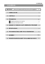
Page 3: ...OLS 3 PREPARATION 4 SUMMARY OF VISIBLE UV LIGHT OBSERVATION PROCEDURE 5 SPECIFICATIONS 6 TROUBLESHOOTING GUIDE FOR UV OBSERVATION 7 ASSEMBLY 4 5 6 7 8 9 10 11 12 U UVF248A 1 Centering the Mercury Xenon Burner 6 2 Adjusting the Illumination Center 7 8 PREVENTIVE INSPECTION SHEET FOR ILLUMINATION DEVICES 13 ...

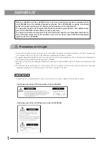
Page 4: ...tter monitors the drive status of the MX61A to prevent accidental irradiation of UV light However care is still required against UV leak from the revolving nosepiece and specimen surface 2 To prevent unexpected irradiation of UV rays be sure to close the idle objective positions of the revolving nosepiece by attaching the caps provided with the revolving nosepiece 3 Leakage of UV light can be prev...

Page 5: ... the main switch of the power supply is set to OFF 8 Be sure to ground the power supply to ensure safety If it is not grounded earthed Olympus can no longer warrant the electrical safety performance of the equipment 9 Before opening the lamp housing for replacing the burner etc be sure to set the main switch of the power supply to OFF disconnect the lamp housing output connector on the power suppl...

Page 6: ...on xenon burner U LH80HGXE Power supply High voltage caution Caution indications Caution indications are affixed at parts where special precaution is required when handling and using the microscope Always heed the cautions Caution indication positions ...

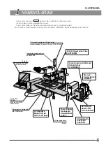
Page 7: ...or for UV observation Recommended TV camera Sony XCD SX910UV Image measuring software analySIS FIVE Active AF unit UV Objective MApo100X for 248 nm UV Rays Objectives for visible light UIS2 UIS series Microscope frame MX61A UV248 Observation Tube U UVF248IM UV Light Guide U UVF2FB U UVF5FB Lamp Housing for Mercury Xenon Burner U LH80HGXE Mercury Xenon Burner UXM80E UV248 Light Source Box U UVF248L...

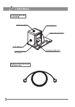
Page 8: ...LBM Centering scope Page 6 UV light guide mount Camera cable connector Caution label Page 1 Lamp housing mount Page 12 BNC connector Motorized shutter light intensity adjustment cable connector Motorized shutter light intensity adjustment cable ...

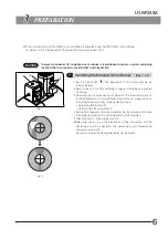
Page 9: ...ation mode and perform the final adjustment to make the image observed on the UV observation monitor brightest 5 Attach the cap in the original position After long hours of use the electrodes will be consumed and the centering position be deviated The centering should therefore be adjusted periodically Be sure to re adjust centering after replacing the burner Fig 2 The motorized control of the MX6...

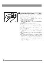
Page 10: ... image is not displayed or abnormally dark the illumination center is deviated In this case the light guide mount should be adjusted 7 Using a Phillips screwdriver loosen slightly the three clamping screws of the UV light guide mount 8 Insert the provided Allen screwdriver alternatively into the two adjustment screws and turn the screws until the brightest observation image is obtained 9 After com...

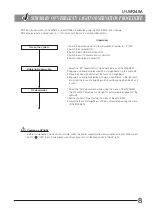
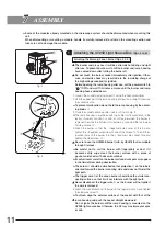
Page 11: ... a visible light objective with low magnification in the light path 3 Place the specimen and adjust the focus and brightness 4 Engage a visible light objective with high magnification in the light path and adjust the focus and brightness Use autofocusing when the AF unit is used 1 Select the DUV observation mode using the menu of the MX2 BSW The MApo100X objective for UV light is automatically eng...

Page 12: ...amp housing U LH80HGXE Mercury xenon burner UXM80E Life Approx 1000 hours Power supply U HX T Optical wavelength 248 4 nm Brightness adjustment 0 to 100 Adjustment with pulse motor drive Shutter Shutter opening closing with pulse motor drive Dimensions weight 170 W x 170 H x 240 D mm approx 3 6 kg ...

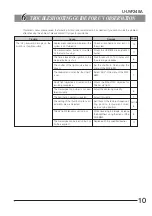
Page 13: ...e stabilizes The shutter of the light source box is closed Set the shutter to Open using the menu of the MX2 BSW The observation mode other than DUV is set Select DUV in the menu of the MX2 BSW No UV light objective is mounted on the revolving nosepiece Mount the MApo100X objective for 248 nm UV light The mercury xenon burner is not cen tered correctly Adjust the centering correctly The illuminati...

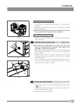
Page 14: ...t the positive pole of the burner into the positive side socket hole and tighten the other screw Be sure to use the UXM80E burner mfd by USHIO that is available through Olympus Be careful not to soil the burner with fingerprints or dust If it becomes dirty wipe clean the burner surface with a piece of gauze moistened with absolute alcohol If contaminants are left on the burner surface dark spots m...

Page 15: ...on the end surfaces 2 Insert the input connector into the UV light guide mount on the UV248 light source box by aligning the positioning marks and tighten the clamping ring 3 Loosen the clamping knob and insert the output connector ƒ all the way Clamp the connection so that the clamping knob is aligned with the positioning reference plane Fig 6 1 Loosen the two lamp housing clamping screws of the ...

Page 16: ...hed on the right or left side Except discharge burners 1 9 Illumination device housing has become deformed cracked or tarnished in any way 10 Lamp cables or wiring parts have become deformed cracked or tarnished in any way We recommend performing Preventive Inspections periodically every time you replace lamps and at least once every 6 months The table below identifies the check items to be observ...

Page 17: ...MEMO ...

Page 18: ...MEMO ...

Page 19: ......

Page 20: ...Manufactured by Distributed by AX7680 03 Printed in Japan on December 25 2012 M 000 03 ...

Reviews: