40/50
D877 MGB Rev01 HE250.docx
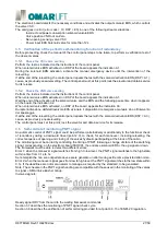
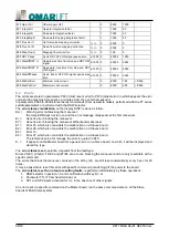
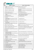
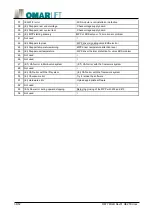
The uphill reference speed are however limited, during operation, to the value corresponding to the nominal
capacity of the pump set in Par.102, increased by a percentage set in Par. 233.
So to ensure to arrive at the maximum flow rate to the piston, you must set the Par. 233 to a value that
compensates for the variability of the pump, and which enables however not exceed the legal limit of
increase of the nominal speed.
It must then set the speed parameter provided with a value equal to or greater than the limit reference speed.
It is generally sufficient to increase the speed prescribed value, the percentage set in Par.233.
The value of the limit reference speed (VRL) uphill, you can still calculate as follows:
VRL = P102 x (P233 / 100 + 1) / (P101) ^2 x P103 / P104 x P109 x 21.22
The system can then work to always make the most of the flow supplied by the pump and direct it to the piston,
blocking the control when the VSC valve reaches a considered closing position. During operation in this
position on the DSP display u6.
In the deceleration position the system acquires the current speed and the control returns to act to calculate
the deceleration necessary to obtain the deceleration distance set in the parameters.
Note:
To reduce the consumption and ensure the functionality of the system, set the low-speed value and of the stop
space so as to limit the stopping time to 1-1.5 s max, according to the following formula:
Time [s] = 2 x Stop space [m] / Low-speed [m/s]
es.:
2 x 0.02 [m] / 0.05 [m/s] = 0.8 s
6.3
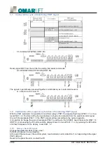
With VVVF drive working valve unit HEVOS HE250
The valve unit Hevos 250 can work in conjunction with a VVVF drive, dedicated for the hydraulics systems,
which works upward for adjust the speed of equipment, by setting the parameter P231 = 1.
In this condition the valve unit remains passive throughout the upstroke and the flow coming from the pump is,
at all times, addressed to the piston.
The substantial differences compared to normal operation concerned solely with the up phase and they are:
1.
In the upward the single input recognized by the board is UP
2.
The test command relief valve is not executed
3.
The upward UCM test command is not executed
4.
During the upstroke the PNP1 monitoring signal is not operated and remains at level 0
5.
The output contact AVV (motor-pump management) is activated for to manage the motor stopping
6.
During the upstroke is not used the ERS solenoid
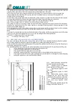
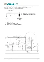
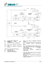
AVV
Motor activation contact from
SCH001 board to control panel
UP
Upward signal to SCH001
board and to VVVF drive input
V
High Speed signal to VVVF
drive input
M
Inspection signal to VVVF
drive input
MOT
Motor-pump power supply
managed by the VVVF drive and
controlled by the upstroke contactors
PI
Parameters generally set on
VVVF drive (see specific VVVF
manual)
Note: During the upstroke travel the
Display of SCH001 shows "ir".


