D877 MGB Rev01 HE250.docx
11/50
2.4
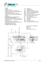
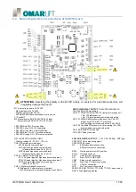
Main components and connections of SCH001 board
ATTENTION:
Reversing the polarity on the 24VDC supply, or inversion f m2 and M3 connectors, will
irreparably damage the board!
M1 Input Voltage board 24-30 VDC
- Max input power 25 W 25 W
- Standby consumption 24VDC:
200mA,300mA with conencted data entry device
F1 Fuse5A-T
M2 Solenoid valve ENR 24-30 VDC 35 W input
Solenoid valve ERS 24-30 VDC 35 W input
SWITCHING RELAY OUTPUT
1A-48VDC/0.25A-250VAC
CN9 AVV Motor Pump starting
CN10 T1 TMAX-TMIN (Par.105-110) temperature range exit:
> Par.105 always active,
< Par. 110 during waiting command only active
CN11 P1 PMAX-PMIN pressure rangeexit, (Par.106-107)
always active if Par.457 =1 otherwise
during waiting command only active if Par. 457=0
CN12 P2 Overload PS pressure limit overcoming, (Par.108)
during waiting command only active
CN13 ERR Stato Error condition
CN14 RDY Ready condition
LD29 LED Red ON = Error condition
LD30 LED Yellow ON= CAN operating
LD31 LED Green ON = Normal condition
LD32 LED Blue ON = Wi-Fi module activated
LD35 LED Orange. ON = SD memory activated
OPTO-ISOLATED DIGITAL INPUT
- Working voltage 20 - 60 VDC - 100 mA
CN6 UP Upward command input
DW Downward command input
HSP Upward high speed command input
(Downward also when Par. 453 = 0)
MSP Upward high speed command input
(Downward also when Par. 453 = 0)
CN7 SFY Motor Pump ON signal
SP1 V3 Speed (together high speed command input)
SP2 V4 Speed (together high speed command input)
SP3 Downward high speed command input
(when Par. 453 = 1)
CN8 -V Digital input negative common
0V Bridge with -V negative for dry contacts
+24V Voltage for dry contacts utilization max 100 mA
VOLTAGE DIGITAL OUTPUT
- V = 23 VDC - 500mA - PNP type
CN15 PNP1 Valve monitoring signal
CN16 PNP2 Not used
M3
ENRsolenoidvalveconnection
ERS solenoid valve connection
RSW
Working selector with 10 position
S1-S2
Confirmation keys
RJ11
Hand terminal connection
SD
Micro SD 2-16 GB FAT32
CN20
Stepper motor connection
USB
Micro-Usb PC direct connection
CAN
CAN net connection
Wi-Fi
Wi-Fi net connection module
ZERO VSC(CN5) TF(CN4), TP1(CN2), TT(CN1), sensor input
DSP1-2 Digit signalyng display


