30/50
D877 MGB Rev01 HE250.docx
4 Manoeuvres of emergency valve unit HEVOS HE250
4.1
Downward movement of the cabin
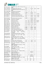
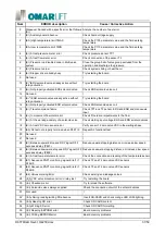
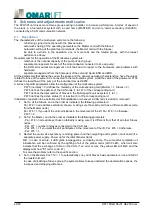
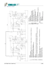
The automatic emergency, in the case of mains failure, must use devices of the valves of the group , that
working during the normal descent maneuver, powered by a battery 24 VDC and 100 W. For the manually
downhill maneuver operate the knob 17, in a clockwise direction, up to a level where the passengers can get
out of the cab.
The regulation of the no. 25 determines the residual pressure of the piston manual lowering. Turn clockwise
to increase pressure, counterclockwise decreases.
To check the minimum pressure adjustment:
-
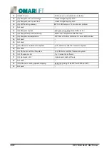
turn on the tap 2 of the gauge cut,
-
turn off the faucet valve assembly 19 and
-
turn the knob 17.
The gauge should show 5-6 bars, if not open the tap 19, adjust the screw no. 25, and then test again.
At the end remember to close the gauge cut tap.
4.2
Upward movement of the cab
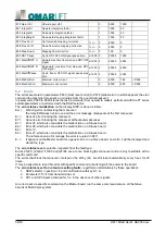
The displacement of the cabin upwards is possible by acting on the hand pump 26, through the appropriate
actuating lever.
If the hand pump is not triggered:
-
Unscrew one turn the vent screw no. 29 and pump until oil comes out from the same screw,
-
tighten the vent screw.
The hand pump is equipped with an overpressure valve which limits the maximum pressure.
The screw no. 27 allows you to adjust the maximum pressure which, normally, must not exceed 2, 3 times the
maximum static pressure.
Turn clockwise to increase pressure, counterclockwise decreases.
To test the pressure relief valve:
-
turn on the tap 2 of the gauge cut,
-
turn off the faucet valve assembly 19 and
-
operate the hand pump 26 until the pressure continues to increase.
The gauge should show the pressure defined by installation specifications.
Otherwise, release the pressure by turning the knob 17, adjust the screw 27 and then test again.
At end remember to close the gauge cut tap.


