OMAX JetMachining® Center Operator’s Guide
400433D-EN
ix
Figures
Page
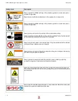
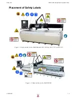
Figure 1-1: Safety Labels for the OMAX Models 2626, 2626|xp, 2652, 5555, and 55100 ............................ 1-3
Figure 1-2: Safety Labels for the OMAX 80160............................................................................................. 1-3
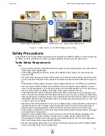
Figure 1-3: Safety Labels for the OMAX 60120............................................................................................. 1-4
Figure 1-4: Safety Labels for the OMAX 80X................................................................................................ 1-4
Figure 1-5: Safety Labels for the OMAX High-pressure Pump...................................................................... 1-5
Figure 1-6: Sound Level Map of OMAX JetMachining Center...................................................................... 1-7
Figure 2-1: OMAX High-Pressure Water Pump ............................................................................................. 2-1
Figure 2-2: OMAX Variable Speed High-Pressure Pump Front View ........................................................... 2-2
Figure 2-3: Pump Control Panel Components................................................................................................. 2-2
Figure 2-4: Front Panel Keypad and Display Screen ...................................................................................... 2-3
Figure 2-5: Pump Control Switches ................................................................................................................ 2-4
Figure 2-6: Pump with Top Lid Open and Front Panel Removed................................................................... 2-5
Figure 2-7: Pump Top View with Lid Open.................................................................................................... 2-6
Figure 2-8: Pump Internal Components on Right Side ................................................................................... 2-6
Figure 2-9: OMAX 80160 JetMachining Center............................................................................................. 2-7
Figure 2-10: The Model 55100 OMAX JetMachining® Center ..................................................................... 2-8
Figure 2-11: The JetMachining Center PC Controller .................................................................................... 2-8
Figure 2-12: Control Panel Operator Switches................................................................................................ 2-9
Figure 2-13: The OMAX 80X JetMachining Center..................................................................................... 2-10
Figure 2-14: OMAX Tilt-A-Jet ..................................................................................................................... 2-10
Figure 2-15: OMAX Precision Optical Locator ............................................................................................ 2-11
Figure 2-16: Waterjet Brick........................................................................................................................... 2-11
Figure 2-17: OMAX Solids Removal System ............................................................................................... 2-12
Figure 2-18: OMAX Inlet Water Chiller ....................................................................................................... 2-12
Figure 2-19: OMAX Drill Head Attachment................................................................................................. 2-13
Figure 2-20: Closed Loop Water Recycling System ..................................................................................... 2-13
Figure 2-21: OMAX Terrain Follower Attached to a Tilt-A-Jet................................................................... 2-14
Figure 3-1: The Abrasivejet Nozzle ................................................................................................................ 3-4
Figure 3-2: The Abrasive Waterjet System ..................................................................................................... 3-5
Figure 3-3: Quality Examples.......................................................................................................................... 3-6
Figure 3-4: Using Tabs Prevents Small Parts from Falling in the Tank.......................................................... 3-7
Figure 3-5: Cutting Nozzle with a Muff Attached........................................................................................... 3-8
Figure 3-6: Selecting Auto Home in OMAX Make ...................................................................................... 3-11
Figure 3-7: White Water Tank Internal View................................................................................................ 3-12
Figure 3-8: White Water Tank Location in OMAX Pump............................................................................ 3-13
Figure 3-9: Verify Correct Mixing Tube Placement ..................................................................................... 3-14
Figure 3-10: Use the Homes Menu Option to Initiate an Auto Home........................................................... 3-14
Figure 3-11: Use Setup to Enable the Soft Limits......................................................................................... 3-15
Figure 3-12: Pump and Nozzle Test Options ................................................................................................ 3-15
Figure 3-13: Example of Both Good and Poor Quality Jet Streams.............................................................. 3-15
Figure 3-14: Comparison of Jet Streams with Different Jewel and Mixing Tube Conditions ...................... 3-16
Figure 3-15: Comparison Spread of Waterjets and Abrasive-waterjets at Different Health States .............. 3-16
Figure 3-16: Nozzle Pressure Test Stop Button ............................................................................................ 3-17
Figure 3-17: Bimba Valve Abrasive Feed Block .......................................................................................... 3-18
Figure 3-18: Setup Menu for Pump and Nozzle Settings .............................................................................. 3-18
Figure 3-19: Settings for Pump and Nozzle .................................................................................................. 3-18
Figure 3-20: Event and Relay Timing Displayed Values.............................................................................. 3-19
Figure 3-21: Material Setup Example............................................................................................................ 3-19
Figure 3-22: Cut, Pierce, and Terrain Follower Setting Options................................................................... 3-20
Figure 3-23: Nozzle Position Functions ........................................................................................................ 3-20
Figure 3-24: Z-axis Height ........................................................................................................................... 3-21
Figure 3-25: Pump and Nozzle Test Options ................................................................................................ 3-22
Figure 4-1: Changing the Pump’s Crankcase Oil ............................................................................................ 4-2
Figure 4-2: Remove the Abrasive Hose from the Nozzle................................................................................ 4-6
Summary of Contents for JetMachining Center 2626
Page 8: ...OMAX JetMachining Center Operator s Guide viii 400433D EN ...
Page 12: ...OMAX JetMachining Center Operator s Guide xii 400433D EN ...
Page 22: ...OMAX JetMachining Center Operator s Guide Safety First 1 10 400433D EN ...
Page 140: ...OMAX JetMachining Center Operator s Guide OMAX Glossary 6 16 400433D EN ...
Page 144: ...OMAX JetMachining Center Operator s Guide Index 4 400433D EN ...

