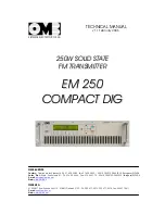
background image

           TECHNICAL MANUAL 

  v1.1 February 2006 

SISTEMAS ELECTRONICOS S.A.

2

2

5

5

0

0

W

W

S

S

O

O

L

L

I

I

D

D

S

S

T

T

A

A

T

T

E

E

F

F

M

M

T

T

R

R

A

A

N

N

S

S

M

M

I

I

T

T

T

T

E

E

R

R

E

E

M

M

2

2

5

5

0

0

C

C

O

O

M

M

P

P

A

A

C

C

T

T

D

D

I

I

G

G

OMB EUROPE: 

Factory:

  Camino de los Albares,14 -Ph. 976.50.35.80, Fax: 976.50.38.55 –  50410 CUARTE DE HUERVA  (Zaragoza) ESPAÑA 

Sales    Dpt.:

  Avda. San Antonio,41– Ph.  976.50.46.96,  Fax: 976.46.31.70 – 50410 CUARTE DE HUERVA (Zaragoza) ESPAÑA 

E-mail:

europa@omb.com

Web:

www.omb.es

OMB USA: 

3100 NW 72nd. Avenue Unit 112 – MIAMI, Florida 33122 – Ph.: 305 477-0973, 305 477-0974, Fax: 305 477-0611 

E-mail:

usa@omb.com

Web:

www.omb.com

Summary of Contents for EM 250 COMPACT DIG

Page 1: ...G OMB EUROPE Factory Camino de los Albares 14 Ph 976 50 35 80 Fax 976 50 38 55 50410 CUARTE DE HUERVA Zaragoza ESPA A Sales Dpt Avda San Antonio 41 Ph 976 50 46 96 Fax 976 46 31 70 50410 CUARTE DE HUE...

Page 2: ...OMB ESPA A Av San Antonio 41 50410 Cuarte de Huerva ZARAGOZA ESPA A Website http www omb com e mail europa omb com Tlf 34 976 50 46 96 Fax 34 976 46 31 70 SISTEMAS ELECTR NICOS N Es01 022 N Es01 E021...

Page 3: ...40 C for Sound Broadcast equipments 6 In case of operation at abnormally high or extremely high temperatures over 30 to 40 C it is obligatory to install a forced cooling system that will keep tempera...

Page 4: ...ge of equipments within inadequate warehouses or outdoors once equipments are delivered to transportist agency About Projects________________________________________________________________ 1 O M B Si...

Page 5: ...ctr nicos S A of the Guarantee Activation Manual returned to OMB by Customer If such Document is not received this Warranty will be voided All repairings or adjustments covered by this Warranty are fr...

Page 6: ...chnical specifications and description of the equipment s features SECTION 2 DESCRIPTION OF INTERNAL MODULES 14 Contains a deep description of the system operation including lists of components schema...

Page 7: ...FM Transmitter Sistemas Electr nicos S A EM 250 COMPACT DIG Technical Manual v1 1 February 2006 2 S Se ec ct ti io on n 0 0 G GE EN NE ER RA AL L R RE EC CO OM MM ME EN ND DA AT TI IO ON NS S...

Page 8: ...placement always refer to User s Manual To avoid explosion do not operate this equipment in an explosive atmosphere To avoid personal injury do not remove the product covers or panels Do not operate t...

Page 9: ...ATION TECHNIQUE Step 1 Check the victim for unresponsiveness If there is no response immediately call for medical assistance and then return to the person Step 2 Position the person flat on their back...

Page 10: ...Cover burned surface with a clean dressing Remove all clothing from the injured area but cut around any clothing that adheres to the skin and leave it in place Keep the patient covered except the inj...

Page 11: ...IG Technical Manual v1 1 February 2006 6 CONTENTS 1 1 Introduction 7 1 2 Description 7 1 3 Front panel 9 1 4 Rear panel 11 1 5 Inner layout 12 1 6 Technical specifications 13 S Se ec ct ti io on n 1 1...

Page 12: ...are once again they must be done by skilled personnel fitted with proper instrumentation and service documentation Improperly tampering with the settings may harm the apparatus or jeopardize the guar...

Page 13: ...d to remotely control the transmitter Above Figure 1 1 shows us the external view of Modulator Exciter s cabinet whose control panel has been simplified to a maximum being Microcontroller in charge of...

Page 14: ...and control elements Fig 1 2 TRANSMITTER CONTROL PANEL These supervision andcontrol elements are numbered in Figure 1 2 as follows 1 ON STBY switch This ON STANDBY key do not power off equipment whic...

Page 15: ...ice versa 5 Twin row Alphanumeric dot matrix LCD display working directly with Microcontroller unit 6 DISPLAY CONTRAST potentiometer to adjust LCD screen backlighting to a comfortable contrast level i...

Page 16: ...former wired signals inverted to the port it needs a simple straight wired serial cable with appropriate connectors usually a female DB 9 or DB 25 female to the PC port and a male DB9 connector at th...

Page 17: ...easily and quickly replaced in case of failure Fig 1 4 EM 250 COMPACT DIG TRANSMITTER UPPER VIEW WITH COVER REMOVED Units can be easily identified according with their respective position within cabi...

Page 18: ...PTION AT 250W RF OUTPUT LEVEL 600 VA 480W OPERATING TEMPERATURES RANGE 0 to 35 C recomm 10 to 45 C max MOUNTING DIMENSIONS W O HANDLES Width 19 Height 3RU in standard 19 Rack DIMENSIONS 483mm width x...

Page 19: ...on 15 2 2 Audio processor and R F control main board 19 2 3 Stereo encoder optional 24 2 4 R F Exciter unit 27 2 5 R F Power Amplifier module 30 2 6 Control unit and display board 41 2 7 Power supply...

Page 20: ...uxiliary For the detailed description of each module on the following pages always refer to the corresponding electrical diagram included in this section Note the manufacturer reserves the right to ch...

Page 21: ...Date Drawn Checked Name Standards Signature Scale Ttle Drawing nr Replace Replaced with Sistemas Electr nicos S A OMB Eng Dpt EM 250 COMPACT DIG General cabinet layout...

Page 22: ...Date Drawn Checked Name Standards Signature Scale Ttle Drawing nr Replace Replaced with Sistemas Electr nicos S A OMB Eng Dpt EM 250 COMPACT DIG Inner layout...

Page 23: ...Dpt EM 250 COMPACT DIG General wiring diagram 1 2 3 4 5 6 7 8 A B C D 8 7 6 5 4 3 2 1 D C B A Drawn Checked Standards Date Name Signature Scale Title Drawing nr Replace Replaced with Sistemas Electr n...

Page 24: ...nd drives the third channel of the electronic attenuator Fig 2 1 MAIN BOARD IS SITUATED IN THE REAR LEFT SECTION OF CABINET On the lower left of the diagram are the RS232 interface IC5 and the paralle...

Page 25: ...then sent to the stereo encoder circuit s input sections if present At the same time the signal on the monaural right channel path is sent to a low pass filter consisting of the section built around I...

Page 26: ...pt EM 250 COMPACT DIG MAINBOARD I O R F Control Section 1 2 3 4 5 6 7 8 A B C D 8 7 6 5 4 3 2 1 D C B A Drawn Checked Standards Date Name Signature Scale Title Drawing nr Replace Replaced with Sistema...

Page 27: ...g Dpt EM 250 COMPACT DIG MAINBOARD LF Process Section 1 2 3 4 5 6 7 8 A B C D 8 7 6 5 4 3 2 1 D C B A Drawn Checked Standards Date Name Signature Scale Title Drawing nr Replace Replaced with Sistemas...

Page 28: ...Date Drawn Checked Name Standards Signature Scale Title Drawing nr Replace Replaced with Sistemas Electr nicos S A 01 11 04 OMB Eng Dpt EM 250 COMPACT DIG Mainboard...

Page 29: ...ow pass filter follows to remove higher order harmonic products This filter is also made with highly precise active circuitry built around IC5 and IC6a b The latter section c of IC6 performs phase equ...

Page 30: ...OMB Eng Dpt EM 250 COMPACT DIG Stereo encoder 1 2 3 4 5 6 7 8 A B C D 8 7 6 5 4 3 2 1 D C B A Drawn Checked Standards Date Name Signature Scale Title Drawing nr Replace Replaced with Sistemas Electr n...

Page 31: ...Date Drawn Checked Name Standards Signature Scale Title Drawing nr Replace Replaced with Sistemas Electr nicos S A 01 11 04 OMB Eng Dpt EM 250 COMPACT DIG Stereo encoder...

Page 32: ...stage This latter is composed by two small MOSFET transistors TR9 and TR10 and attains some 900mW output level 29dBm over the full FM range To correctly operate TR9 and TR10 require a gate bias volta...

Page 33: ...4 OMB Eng Dpt EM 250 COMPACT DIG FM Exciter 1 2 3 4 5 6 7 8 A B C D 8 7 6 5 4 3 2 1 D C B A Drawn Checked Standards Date Name Signature Scale Title Drawing nr Replace Replaced with Sistemas Electr nic...

Page 34: ...Date Drawn Checked Name Standards Signature Scale Title Drawing nr Replace Replaced with Sistemas Electr nicos S A 01 11 04 OMB Eng Dpt EM 250 COMPACT DIG FM Exciter...

Page 35: ...LIFIER MODULE RF Power module includes a driver stage and an output amplifier stage Figure 2 3 above shows the general arrangement of this power amplifier module Numbered elements are as follows 1 Coo...

Page 36: ...42 transistor working in class AB configuration Numbered elements corresponds to the following description 1 Input matching attenuator circuit 2 BLF 242 RF Driver transistor 3 Bias control circuit 4 I...

Page 37: ...follows 1 Input splitter transformer and coupling circuit 2 Bias adjustment potentiometer 3 Bias regulator circuit 4 MOSFET push pull arranged twin transistor capsule 5 Output combiner transformer an...

Page 38: ...nitor for measurements purposes The transistor gate is biased by a Zener network and a resistor to set 50mA drain current with 2 8Vgs Varying the control voltage towards a negative supply progressivel...

Page 39: ...C10 2 Zener diode 30V o 28V 1N5363B 30V D1 1 Rectifier diode SMD BAS16 D2 1 Zener diode 5V1 SMD BZX84 C5V1 D3 1 Wire 1mm Cu enamelled Material L1 L2 230mm approx Inductance 6 turns ext 6mm int 4mm 1m...

Page 40: ...Sistemas Electr nicos S A R1 1R 2W R3 1K8 0 5W D2 1N5363B 30V o 28V C1 100nF C2 10uF GND GND GND 28V Q2 TIP3055 R2 1R 2W Q1 BLF242 C6 68pF C3 150pF C7 1nF C9 10nF C8 1nF C4 220pF C5 18pF C10 10nF R4...

Reviews: