


FM Transmitter
Sistemas Electrónicos S.A EM 250 COMPACT DIG
Technical Manual - v1.1 - February 2006
12
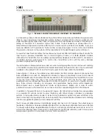
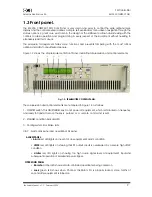
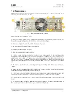
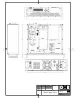
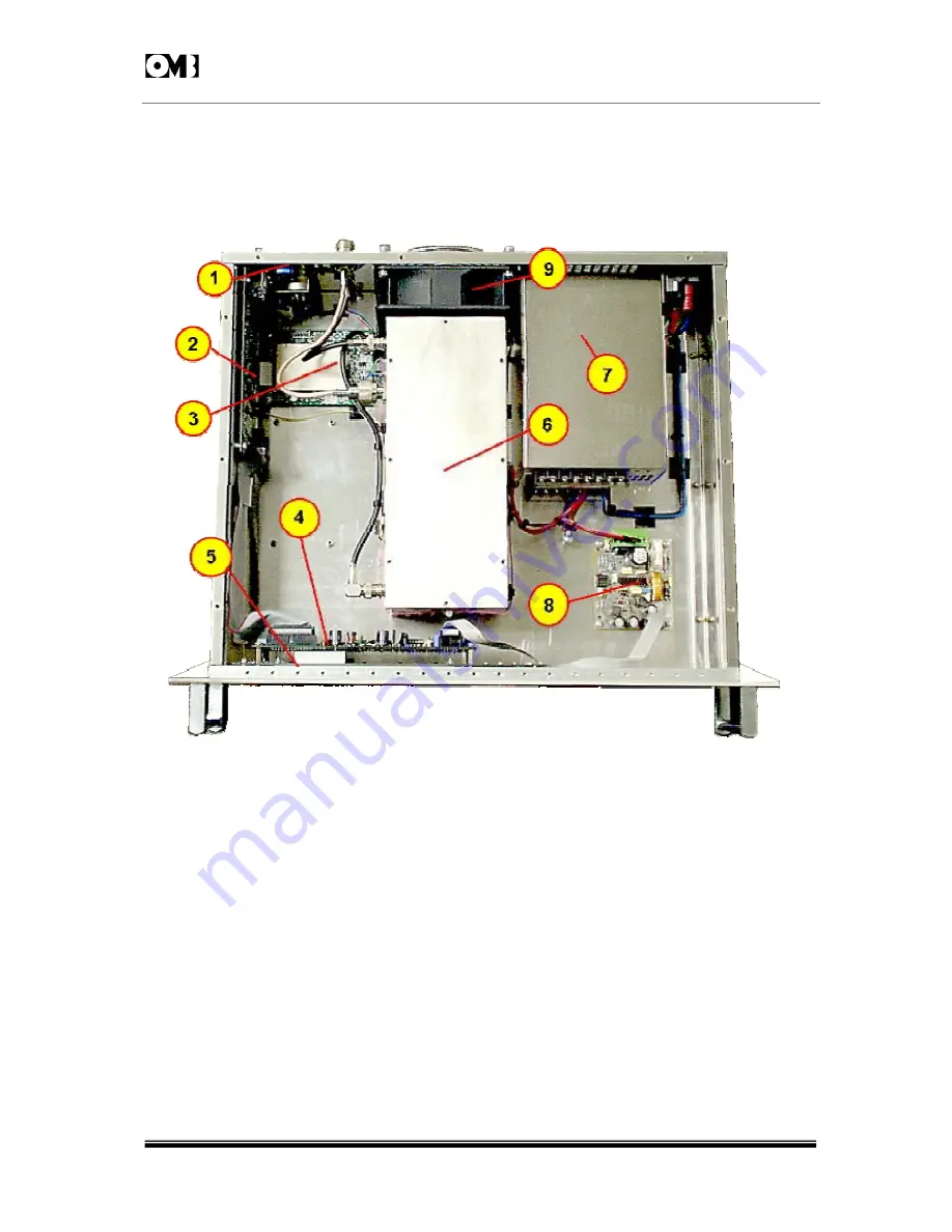
1.5 Inner layout.
Figure 1-4 below shows space occupied and allocation of the different units and PC boards within
equipment, and internal arrangement of cabinet. All boards and units can be easily and quickly
replaced in case of failure:
Fig. 1-4: EM-250 COMPACT DIG TRANSMITTER.UPPER VIEW WITH COVER REMOVED.
Units can be easily identified according with their respective position within cabinet, as numbered in
above Figure 1-4 :
1
- Audio Input board.
2
- Main board.
3
- RF Exciter and Modulation Unit.
4
- Microcontroller Unit.
5
- LCD Display Unit.
6
- RF Power Amplifier Module.
7
- SP-500/48 Main Switching Power Supply.
8
- +15V
DC
Auxiliary Power Supply.
Space
reserved for
optional
Stereo
encoder


