


FM Transmitter
Sistemas Electrónicos S.A EM 250 COMPACT DIG
Technical Manual - v1.1 - February 2006
20
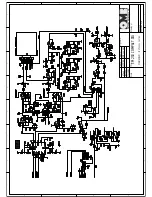
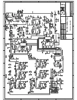
Let's now go to the second sheet of this diagram. Beginning from the lower left side,we find IC8, which
makes a 3-channel digitally controlled attenuator. It separately manages left, right and auxiliary
channel, while the externalmultiplex signal is processed in the same channel as the right one. Three
buffer/amplifiers follow each channel: IC7a, IC8a and IC12a. The output of the first two amplifiers drive
the pre-emphasis stages, whose time constants can be digitally set at 0, 50 and 75µs, through the
analog gates of IC9. A limiter stage follows this arrangement, built around D8 and D9 diodes acting as
clippers. By acting on the limiter ’s reference voltage driven by the Microcontroller through IC13a, the
limiter threshold level +Vl and -Vl can be adjusted. RT4, if present, impose a top limit to the limiter.
The signal is then sent to the stereo-encoder circuit ’s input sections if present. At the same time, the
signal on the monaural right channel path is sent to a low-pass filter, consisting of the section built
around IC10 and IC11, which attenuates the frequencies above 15kHz.
The switch IC14 selects the signal issuing from the non-pre-emphasized input section through R124 or
from the pre-emphasis-and-filter section through R128 or from the stereo-encoder through R131.
IC12b buffers the chosen signal and mixes it with that issuing from the auxiliary channel. When
required, the diode D17 further limits the resulting total signal.The latter is then sent to the FM
modulating/exciting circuit via IC12c buffer circuit and adjusted in level by RT6 as required. A separate
section of IC12 separately buffers the modulation signal for monitoring purpose,and sends it to the
modulation output connector.
IC15 deserialize the digital signal sent by the Microcontroller, to control the transmission channels with
IC14 and preemphasis action with IC9. Two output lines from IC15 are used to latch the remote output
lines "
FAIL
"and "
ON THE AIR
".


