


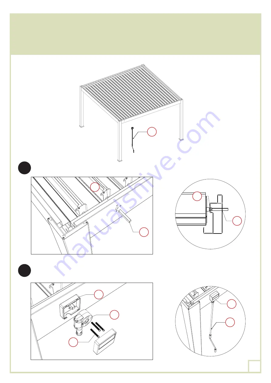
Insérer le cylindre
PO
au travers de la poutre comme indiqué sur le schéma, puis pousser jusqu’à
emboitement avec l’ergot de la lame principale
KO
.
Associer et visser la première partie du boitier
OO
avec la gearbox
NO
sur la poutre principale
BO
,
avec les 3 boulons
YO
, à l’aide de la clé Allen
ZO-3
ou d’une visseuse et de l’embout
ZO-4
.
HO
HO
PO
PO
KO
KO
OO
OO
NO
YO
1
2
17
Summary of Contents for 15-728486
Page 8: ...8 PLAN DE MONTAGE dimensions en mm 5 2 4 5 2 5245 2 3706 3706 8...
Page 15: ...KO KO KO BO LO 1 LO 1 BO 1 1 KO BO LO 1 LO 1 BO 1 2 KO LO 1 GO GO GO GO 15...
Page 26: ...8 FOOTING MEASUREMENT dimensions in mm 5 2 4 5 2 5245 2 3706 3706 26...
Page 33: ...KO KO KO BO LO 1 LO 1 BO 1 1 KO BO LO 1 LO 1 BO 1 2 KO LO 1 GO GO GO GO 33...
Page 44: ...8 PLAN DEL MONTAJE DIMENSIONES EN MM 5 2 4 5 2 5245 2 3706 3706 44...
Page 51: ...KO KO KO BO LO 1 LO 1 BO 1 1 KO BO LO 1 LO 1 BO 1 2 KO LO 1 GO GO GO GO 51...
Page 62: ...8 PIANO DI MONTAGGIO DIMENSIONI IN MM 5 2 4 5 2 5245 2 3706 3706 62...
Page 69: ...KO KO KO BO LO 1 LO 1 BO 1 1 KO BO LO 1 LO 1 BO 1 2 KO LO 1 GO GO GO GO 69...


