


FO
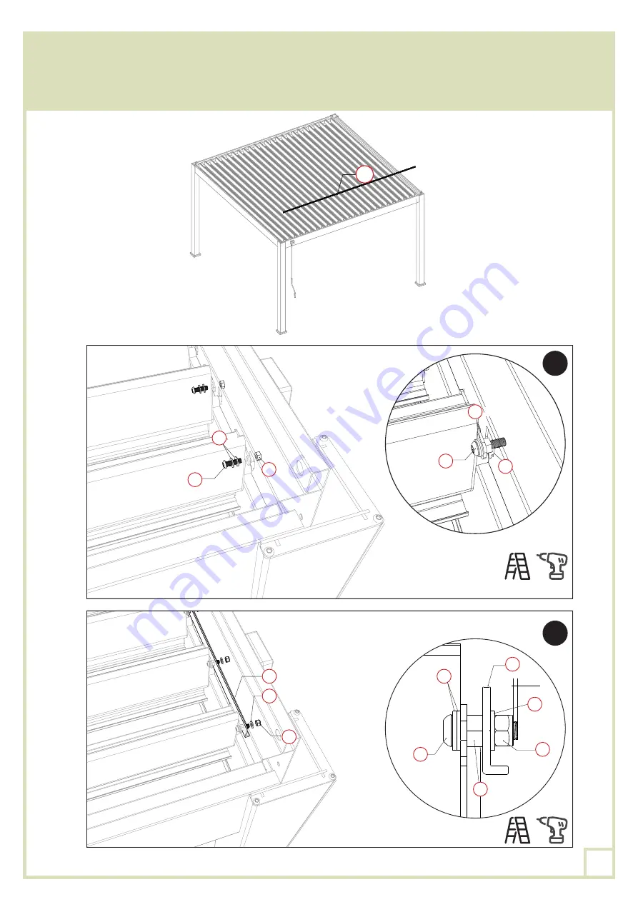
Fixer la visserie
XO-2
,
VO
et
UO-1
dans chaque cache-lame, comme indiqué sur le schéma.
Puis, fixer la barre de connexion
FO
sur toutes les lames avec les rondelles
VO
et les écrous
UO
, à
l’aide d’une visseuse et de l’embout PH2
ZO-1
et de la clé
ZO-5
pour maintenir l’écrou.
UO-1
UO-1
VO
VO
XO-2
XO-2
×2
×2
1
2mm
UO-1
VO
VO
VO
UO
UO
FO
FO
XO-2
2
18
Summary of Contents for 15-728486
Page 8: ...8 PLAN DE MONTAGE dimensions en mm 5 2 4 5 2 5245 2 3706 3706 8...
Page 15: ...KO KO KO BO LO 1 LO 1 BO 1 1 KO BO LO 1 LO 1 BO 1 2 KO LO 1 GO GO GO GO 15...
Page 26: ...8 FOOTING MEASUREMENT dimensions in mm 5 2 4 5 2 5245 2 3706 3706 26...
Page 33: ...KO KO KO BO LO 1 LO 1 BO 1 1 KO BO LO 1 LO 1 BO 1 2 KO LO 1 GO GO GO GO 33...
Page 44: ...8 PLAN DEL MONTAJE DIMENSIONES EN MM 5 2 4 5 2 5245 2 3706 3706 44...
Page 51: ...KO KO KO BO LO 1 LO 1 BO 1 1 KO BO LO 1 LO 1 BO 1 2 KO LO 1 GO GO GO GO 51...
Page 62: ...8 PIANO DI MONTAGGIO DIMENSIONI IN MM 5 2 4 5 2 5245 2 3706 3706 62...
Page 69: ...KO KO KO BO LO 1 LO 1 BO 1 1 KO BO LO 1 LO 1 BO 1 2 KO LO 1 GO GO GO GO 69...


