


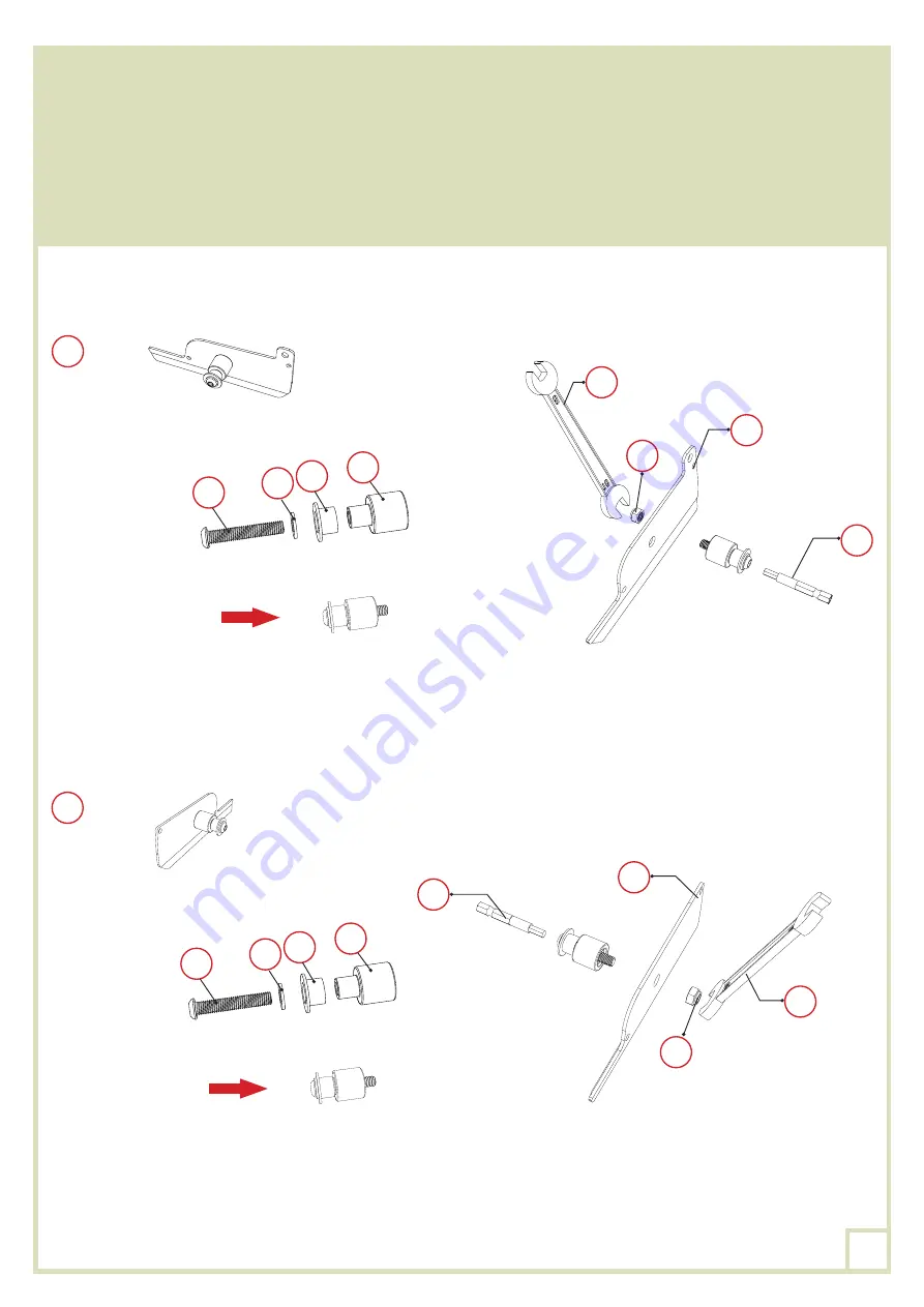
Confecciona y fija el pasador correspondiente al conjunto
XO,VO
,
MO,MO-1
y
UO
en las tapas de
las lamas
LO
y
LO-1
. Asegúrate de que el pasador está instalado en la dirección correcta tanto para
la pieza
LO
como para la
LO-1
, tal y como se muestra en el diagrama.
Utiliza un destornillador y la punta
ZO-2
para ayudar a insertar el perno
XO
en la tuerca
UO.
Para
evitar lesiones y facilitar al máximo la operación, recomendamos sujetar la tuerca con la llave
ZO-5
durante la misma.
×24
LO
×25
LO
LO
UO
VO
VO
MO-1
MO-1
ZO-5
ZO-2
MO
MO
XO
XO
LO-1
UO
ZO-5
ZO-2
48
Summary of Contents for 15-728486
Page 8: ...8 PLAN DE MONTAGE dimensions en mm 5 2 4 5 2 5245 2 3706 3706 8...
Page 15: ...KO KO KO BO LO 1 LO 1 BO 1 1 KO BO LO 1 LO 1 BO 1 2 KO LO 1 GO GO GO GO 15...
Page 26: ...8 FOOTING MEASUREMENT dimensions in mm 5 2 4 5 2 5245 2 3706 3706 26...
Page 33: ...KO KO KO BO LO 1 LO 1 BO 1 1 KO BO LO 1 LO 1 BO 1 2 KO LO 1 GO GO GO GO 33...
Page 44: ...8 PLAN DEL MONTAJE DIMENSIONES EN MM 5 2 4 5 2 5245 2 3706 3706 44...
Page 51: ...KO KO KO BO LO 1 LO 1 BO 1 1 KO BO LO 1 LO 1 BO 1 2 KO LO 1 GO GO GO GO 51...
Page 62: ...8 PIANO DI MONTAGGIO DIMENSIONI IN MM 5 2 4 5 2 5245 2 3706 3706 62...
Page 69: ...KO KO KO BO LO 1 LO 1 BO 1 1 KO BO LO 1 LO 1 BO 1 2 KO LO 1 GO GO GO GO 69...


