


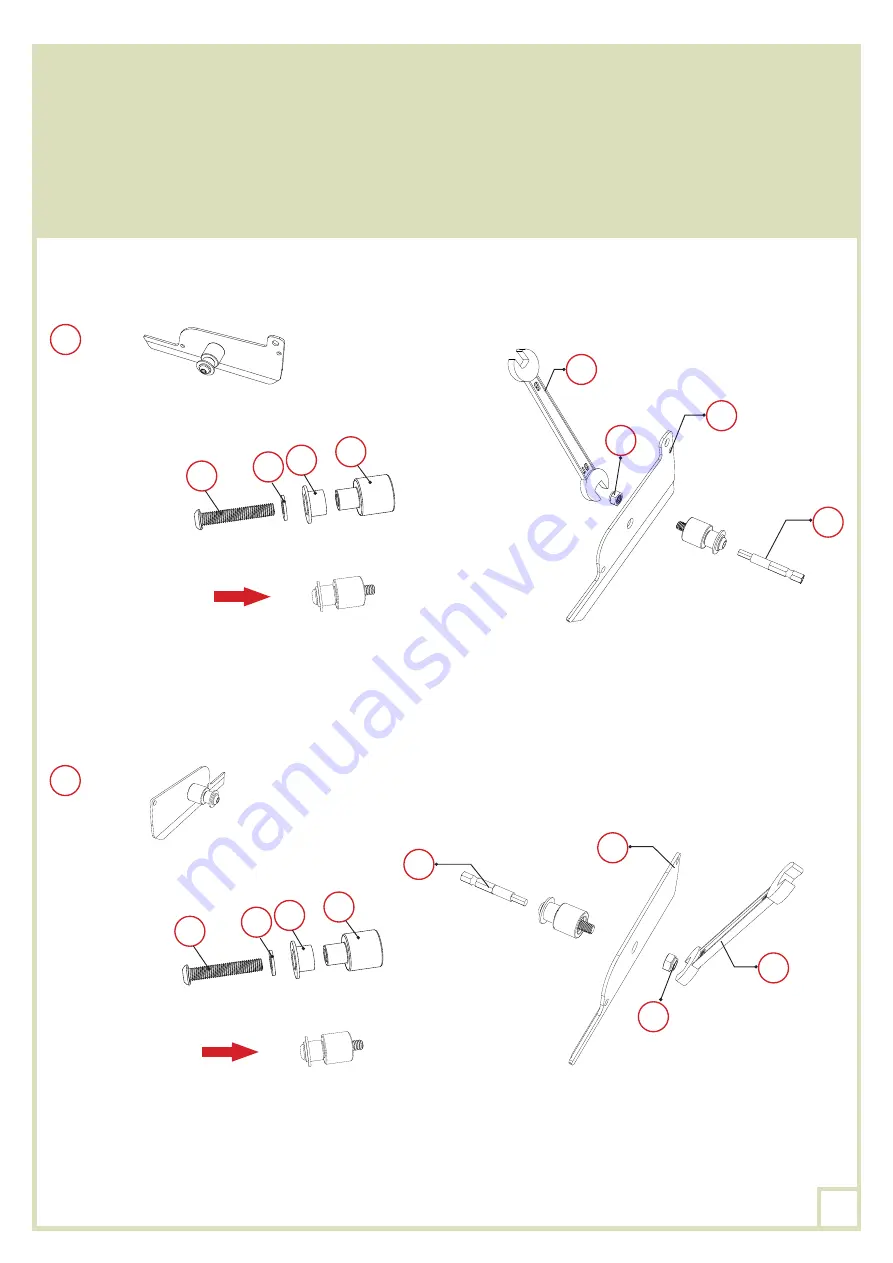
Montate e fissate il perno corrispondente all’insieme delle parti
XO,VO
,
MO,MO-1
e
UO
nei copri-
lamella
LO
e
LO-1
. Assicuratevi che il perno sia installato correttamente nella giusta direzione per la
parte
LO
e per la parte
LO-1
, come indicato nello schema.
Utilizzate l’avvitatore e la punta
ZO-2
per inserire il bullone
XO
nel dado
UO
.Per evitare lesioni e
rendere l’operazione non troppo difficile, si consiglia di tenere il dado con la chiave
ZO-5
durante
questa manipolazione.
×24
LO
×25
LO
LO
UO
VO
VO
MO-1
MO-1
ZO-5
ZO-2
MO
MO
XO
XO
LO-1
UO
ZO-5
ZO-2
66
Summary of Contents for 15-728486
Page 8: ...8 PLAN DE MONTAGE dimensions en mm 5 2 4 5 2 5245 2 3706 3706 8...
Page 15: ...KO KO KO BO LO 1 LO 1 BO 1 1 KO BO LO 1 LO 1 BO 1 2 KO LO 1 GO GO GO GO 15...
Page 26: ...8 FOOTING MEASUREMENT dimensions in mm 5 2 4 5 2 5245 2 3706 3706 26...
Page 33: ...KO KO KO BO LO 1 LO 1 BO 1 1 KO BO LO 1 LO 1 BO 1 2 KO LO 1 GO GO GO GO 33...
Page 44: ...8 PLAN DEL MONTAJE DIMENSIONES EN MM 5 2 4 5 2 5245 2 3706 3706 44...
Page 51: ...KO KO KO BO LO 1 LO 1 BO 1 1 KO BO LO 1 LO 1 BO 1 2 KO LO 1 GO GO GO GO 51...
Page 62: ...8 PIANO DI MONTAGGIO DIMENSIONI IN MM 5 2 4 5 2 5245 2 3706 3706 62...
Page 69: ...KO KO KO BO LO 1 LO 1 BO 1 1 KO BO LO 1 LO 1 BO 1 2 KO LO 1 GO GO GO GO 69...


