background image

Pag. 10

1.

Controllare che tutti i collegamenti siano corretti.

2.

Alimentare il posizionatore.

N.B.

Il posizionatore viene fornito per la rotazione in

senso antiorario. Per invertire il senso di rotazione è
sufficente seguire la procedura descritta al paragrafo
10.

3.

Inviare un segnale di 3 psi o 4 mA al posizionatore e

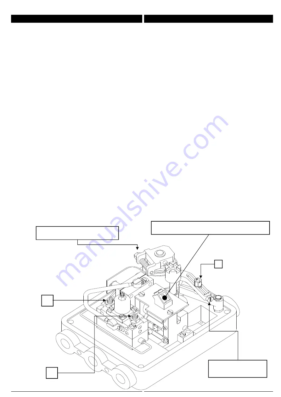
agire sulla vite di zero (Fig. 7) sino a far partire la
valvola.

4.

Girare la vite di zero, molto lentamente, in senso

contrario sino a portare la valvola in posizione di inizio
corsa.

5.

Inviare un segnale di 15 psi o 20 mA al posizionatore

e verificare l'apertura della valvola.

6.

Se la corsa della valvola non corrisponde a quella

desiderata,

allentare il dado "1"

e agire sulla vite

di correzione campo. Ruotare la vite in senso orario per
aumentare il campo e in senso opposto per diminuirlo.
Durante questa operazione tenere presente che ogni
rotazione completa della vite, corrisponde a circa 2° di
rotazione della valvola. Serrare il dado "1".

7.

Inviare un segnale di 3 psi o 4 mA al posizionatore e

ripetere la correzione di zero.

8.

Inviare un segnale di 15 psi o 20 mA al posizionatore

e verificare l'apertura della valvola. Se necessario
ripetere le operazioni da 6 a 7 sino al conseguimento
dei valori desiderati.

1.

Check the piping connections

2.

Feed the positioner.

Note:

The positioner is suplied with anticlockwise

rotation as standard. To reverse the way of rotation
follows the procedure on item 10.

3.

Send a 3 psi or 4mA signal to the positioner

reaching the actuator starting point, by shifting the zero
adjustment screw (Fig.7)

4.

Turn slightly the screw (Fig. 7) to the opposite

direction until the actuator is come back to the starting
position.

5.

Send a 15 psi or 20mA signal to the positioner and

check the valve opening.

6.

In case of the valve stroke is still incorrect, then

release the screw nut "1"

and turn the span

adjustment screw (Fig. 7). Turn that screw on
clockwise

direction

to

increase

the

span

or

anticlockwise to reduce it. During the operation mind
that any complete turn of screw means about 2° of
valve rotation angle. Now lock the nut "1".

7.

Repeat the zero adjustment still sending a 3 psi or

4mA signal to the positioner.

8.

Send again a 15 psi or 20mA signal to the positioner

and check the valve opening.
If necessary, repeat the operation of items 6 and7 until
the right calibration is reached.

CORREZIONE CAMPO

SPAN ADJUSTMENT

1

Fig.  7 (R99E)

7. MESSA IN FUNZIONE

7. COMMISSIONING

A

B

CORREZIONE ZERO
ZERO ADJUSTMENT

CONNESSIONI ELETTRICHE 4÷20mA

ELECTRICAL CONNECTIONS 4÷20mA

Summary of Contents for PVP11BE.1

Page 1: ...OMOTORI ROTANTI ROTARY VALVE POSITIONERS R99P R99E PVP11BE 1 ATEX Our products are manufactured under ISO 9001 Quality Assurance System approved by CSQ certified under nr 9190 OMC2 FIRST ISSUE 1994 08...

Page 2: ...RE 4 CORDINATION BETWEEN POSITIONER AND ACTUATOR 4 1 ATTUATORI A DOPPIO EFFETTO 4 1 DOUBLE ACTING ACUATORS 4 2 ATTUATORI A SEMPLICE EFFETTO 4 2 SINGLE ACTING ACTUATORS 5 CONNESSIONI ELETTRICHE E PNEUM...

Page 3: ...OTEZIONE EN 60529 PESO CON MANOMETRI TEMPERATURA AMBIENTE R99P R99E PVP11BE 1 TEMPERATURA DI STOCCAGGIO SEGNALE DI COMANDO R99P R99E PVP11BE 1 CONNESSIONI ELETTRICHE R99E e PVP11BE 1 Ui Ii Pi Impedenz...

Page 4: ...est effected with pipe 6 x 8 mm ALIMENTAZIONE 6 BAR max 0 8 Nm h 6 BAR SUPPLY max 0 8 Nm h ALIMENTAZIONE 8 BAR max 1 0 Nm h 8 BAR SUPPLY max 1 0 Nm h ALIMENTAZIONE 10 BAR max 1 5 Nm h 10 BAR SUPPLY ma...

Page 5: ...a seguendo la Fig 3 1 2 The positioners are equipped of universal bracket wich allows to fit the unit of any actuator in according to NAMUR standards easily changing the position of fixing screws see...

Page 6: ...B POSIZIONI VITI DI FISSAGGIO L BRACKETS MOUNTING B A 80 mm 20 mm 80 mm 30 mm 130 mm 30 mm 130 mm 50 mm TAB 3 1 3 R99 R99 R99 R99 ATTUATORE ACTUATOR ATTUATORE ACTUATOR ATTUATORE ACTUATOR ATTUATORE AC...

Page 7: ...orte P1 e P2 dello stesso Collegare le uscite del posizionatore OUT1 e OUT2 alle porte dell attuatore secondo la rotazione voluta vedi Fig 4 1 1 e Fig 4 1 2 Il posizionatore viene fornito per la rotaz...

Page 8: ...P1 Al fine di sfruttare al meglio le caratteristiche del posizionatore si raccomanda di collegare sempre la restante porta P2 con l uscita OUT2 del posizionatore Nel momento in cui viene a mancare l...

Page 9: ...atic connections are easily accessible externally see Fig 2 4 To ensure trouble free use of this positioner the air supply should be conditioned to remove dirt and moisture A filter regulator should b...

Page 10: ...ipetere le operazioni da 6 a 7 sino al conseguimento dei valori desiderati 1 Check the piping connections 2 Feed the positioner Note The positioner is suplied with anticlockwise rotation as standard T...

Page 11: ...La massima velocit si ottiene togliendo del tutto le viti A e B A splitted opening closing speed adjustment of the valve should be made by means the nut screws A B Fig 7 To rise the valve speed relea...

Page 12: ...1 11 1 R99E PVP11BE 1 972IPT 072 46 072 42 200 25 200 32 200 41 988SRE 988CAE 200 30 200 42 110 145 200 31 200 16 972S11 972GMZ 200 19 200 44 110 164 073 105 073 106 PVP11BE 1 PVP11BE 1 R99E R99E INP...

Page 13: ...Pag 13 972IPT 072 46 072 42 200 25 200 41 988SRP 988CAP 200 29 200 42 200 16 972S11 972GMZ 11 2 R99P 11 2 R99P 200 19...

Page 14: ...rit contenute nell aria di alimentazione olii polveri acqua ecc sono la principale causa delle anomalie di funzionamento del posizionatore Esse si depositano all interno del posizionatore stesso ostru...

Page 15: ...re e correggere Mancanza aria di alimentazione Controllare e correggere Positioner with wrong control action Pneumatic connection between actuator and positioner has been inverted Reverse its position...

Reviews: