Pag. 11
Parecchie applicazioni richiedono che la valvola esegua i 90°
di corsa con il segnale in ingresso ridotto del 50% (3÷9psi o
9÷15psi per R99P ; 4÷12mA o 12÷20mA per R99E). Nel caso
sia richiesta questa operazione è sufficiente
allentare il
dado "1"
Fig. 7, far compiere alla vite di regolazione campo
circa 22 giri completi in senso orario e ripetere la procedura
del capitolo precedente sostituendo i segnali in ingresso.
Many applications require the 90° of valve stroke with a 50%
reduced input signal (3÷9 psi or 9÷1 5 for R99P; 4÷12 or
12÷20 mA for R99E).
In this case
release the screw nut "1"
(Fig. 7) and turn
the span adjustment of about 22 periods on clockwise
direction and repeat the procedure of the previous chapter
(by using the suitable input signals).
8. FUNZIONAMENTO IN SPLIT RANGE
8. SPLIT RANGE OPERATION
Con i posizionatori R99 è possibile regolare separatamente
le velocità di apertura e chiusura della valvola, agendo sulle
viti "A" e"B" Fig.7. Per diminuire le velocità, allentare i dadi di
bloccaggio e ruotare le viti in senso orario. Per aumentare le
velocità, allentare i dadi di bloccaggio e ruotare le viti in
senso antiorario.
La massima velocità si ottiene
togliendo del tutto le viti "A" e"B"
A splitted opening / closing speed adjustment of the valve
should be made by means the nut screws "A" & "B" (Fig.7).
To rise the valve speed, release these nuts and turn the
screw on anticlockwise direction.
The maximum speed
is obtained by removing the nut screws "A" & "B"
completely.
9. REGOLAZIONE VELOCITÀ VALVOLA
9. VALVE SPEED ADJUSTMENT
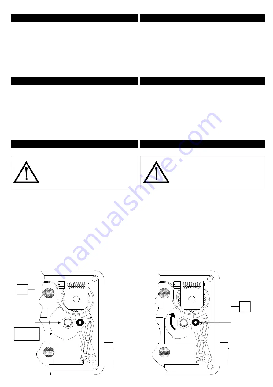
Il posizionatore viene fornito per la rotazione in senso
antiorario (Fig.10.1). Per invertire il senso di rotazione è
sufficente seguire la procedura sotto:
1) Allentare il dado blocca camma "C"
2) Ruotare la camma in senso orario, portando il cuscinetto
"D" all'incirca nella posizione in Fig.10.2
3) Serrare il dado "C".
4) Ripetere la procedura del capitolo 7
The positioner is provided with anti-clockwise rotation (see
fig. 10.1). To reverse the direction of rotation see the
following items:
1) Release the nut "C"
2) Rotate the cam wheel as the arrow on Fig.10.2 (clockwise
rotation). Hold the bearing on "D" position.
3) Lock the nut "C".
4) Now repeat the procedure mentioned on chapter 7.
10. INVERSIONE DEL SENSO DI ROTAZIONE
10. ROTATION REVERSING
C
D
CAMMA
CAM
Fig. 10.1
Fig. 10.2
ATTENZIONE!
Prima di compiere questa manovra,
assicurarsi che il posizionatore non sia
alimentato.
CAUTION!
Before be over this operate, make sure
that the positioner has not in pressure.


