background image

8

Installation

TRANSPORT

Transport shall be carried out by qualified personnel so as to avoid any damage to the machine and any of its 

components. In particular:

• 

All the guards, covers and doors must be properly closed and secured.

•  Use a forklift or transpallet with sufficiently long forks and loading capacity.

The load bearing capacity of the forklift truck must be more than the weight of the machine; check this 

capacity on the plates affixed on the forklift truck and in the operating instructions.

The machine should be transported on a flat and solid floor only, free of unevenness.

INSTALLATION

The machine must be positioned on a hard and level floor. Connection to the power supply must be carried out 

in accordance with the current standards and taking into account the necessary measures in order to avoid the 

dangers of indirect contact and overcurrent. Also check that:

•  The supply voltage is 400 V on the input terminals (L1 - L2 - L3) located inside the electrical control panel.

• 

The machine’s connection to ground is, in fact, connected to the company grounding system.

Make sure the cutter is placed in a sufficiently lit work area (min. 300 lux). Check that there is enough space 

around the machine to move the removable parts and that it is easily accessible for routine and extraordinary 

maintenance (at least 500 mm of free space besides the dimensions of removable parts)

PRELIMINARY CHECK PRIOR TO STARTING-UP

Once the machine has been connected to the mains the following check is necessary:

1. 

Using the jog mode, press the two hand control device (push buttons P), to check that the cutting wire 

moves down towards the work top.

2. 

If the wire moves upwards instead, reverse the electrical connections in the plug (reverse the phase).

3. 

Now check again.

If it is necessary to reverse the phase you must first disconnect the electricity (take the plug out of the 

socket/open the omnipolar switch directly upstream). In all cases this must be done by a specifically 

skilled electrician.

The machine is equipped for the earth-connection of conductive metal masses. The connection must 

be ensured and carried out correctly in accordance with applicable technical standards. The machine 

cannot be used if it is not earthed.

Operations on electrical equipment must only be carried out by qualified technical personnel with 

the necessary electrical engineering skills, after referring to the wiring diagram and the necessary 

conditions in order to avoid electrocution.

Summary of Contents for 45412

Page 1: ...Cheese Cutter Model GR IT 1000 C Item 45412 Instruction Manual Revised 07 05 2022 Toll Free 1 800 465 0234 Fax 905 607 0234 Email service omcan com www omcan com...

Page 2: ...10 12 12 17 18 28 29 30 31 Table of Contents Section General Information Safety and Warranty Technical Specifications Installation Operation Maintenance Electrical Schematics Notes Warranty Registrati...

Page 3: ...e It s of the utmost importance to save these instructions for future reference Also save the original box and packaging for shipping the equipment if servicing or returning of the machine is required...

Page 4: ...este ha sido entrenado en el correcto funcionamiento de esta m quina y sta usando ropa apropiada y autorizada Cualquier modificaci n a la m quina an la la garant a y puede causar da os a las personas...

Page 5: ...on read the Instructions for use and the relevant attached documentation when necessary If in doubt contact an authorized technician INTENDED AND IMPROPER USE OF THE MACHINE The CUTTER is a machine fo...

Page 6: ...al personnel with the necessary electrical engineering skills after referring to the wiring diagram and the necessary conditions in order to avoid electrocution Beware of hazards due to indirect conta...

Page 7: ...ed service technician to repair the equipment locally Unauthorized maintenance will void the warranty Warranty covers electrical and part failures not improper use Please see https omcan com disclaime...

Page 8: ...ork area min 300 lux Check that there is enough space around the machine to move the removable parts and that it is easily accessible for routine and extraordinary maintenance at least 500 mm of free...

Page 9: ...onsidered as such when they feature fixing elements which can only be removed by using a tool The rear and sides of the machine are closed with fixed guards in either a transparent material or metal B...

Page 10: ...ncy pressure The physical environment is as indicated for example correct lighting and noise levels temperature humidity atmospheric contaminants AFTER POWER HAS BEEN SWITCHED ON CHECK THAT Start stop...

Page 11: ...whole cheese to cut 1 Make an incision on the cheese axis 2 with tool B by hand using tool C as a guide Trim the edges of the whole cheese 3 by hand with saw A Take the prepared cheese over the Cutter...

Page 12: ...tions must be taken before any intervention Disconnect the machine from the mains At the end of each intervention Put all the fixed and or interlocked guards back in place at the end of the interventi...

Page 13: ...CUTTING WIDTH LIMIT SWITCH To alter height H of the cutting wire from the work top on which the cheese is move the sensor Ref 2 as follows Counterclockwise to lift the wire Clockwise to lower the wir...

Page 14: ...ssible dangers CHANGING THE CUTTING WIRE To change the cutting wire proceed as follows Remove the wire using the tools supplied A and B Hook the two cables 1 with the ends of the tool A Loosen the dow...

Page 15: ...training on the operating procedures as well as being informed about the possible dangers MAINTENANCE AND CLEANING PRELIMINARY INSTRUCTIONS Only qualified specially trained and authorised personnel sh...

Page 16: ...nd internally on a daily basis Prior to any cleaning operations it is necessary to Disconnect the machine from the power supply mains Do not clean the machine with high pressure water or steam jets Do...

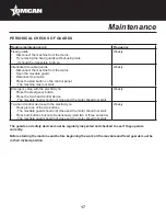
Page 17: ...ss the emergency button Press the two hand control device The movable guard should not close and the motor should not start Weekly Two hand control device with the electricity on Press just one of the...

Page 18: ...18 Electrical Schematics Model GR IT 1000 C 45412 Main Disconnector...

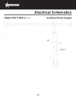
Page 19: ...19 Electrical Schematics Model GR IT 1000 C 45412 Auxiliary Power Supply...

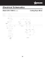
Page 20: ...20 Electrical Schematics Model GR IT 1000 C 45412 Cutting Rope Motor...

Page 21: ...21 Electrical Schematics Model GR IT 1000 C 45412 Forward Contactor...

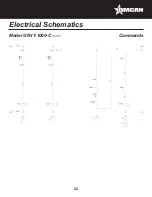
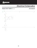
Page 22: ...22 Electrical Schematics Model GR IT 1000 C 45412 Commands...

Page 23: ...23 Electrical Schematics Model GR IT 1000 C 45412 Commands...

Page 24: ...24 Electrical Schematics Model GR IT 1000 C 45412 Machine Safety Relays...

Page 25: ...25 Electrical Schematics Model GR IT 1000 C 45412 Machine Safety Devices...

Page 26: ...26 Electrical Schematics Model GR IT 1000 C 45412 Machine Contemporary Relay...

Page 27: ...27 Electrical Schematics Model GR IT 1000 C 45412 Push Buttons...

Page 28: ...Wire for Reverse KA21 3 21 3 Top Wire KA21 8 21 8 Cut Rope Descent KA22 1 22 1 Climb Cut Rope KA73 2 73 2 Machine Safety Relays KA75 2P 75 2 Machine Contemporaneity Release KM10 2 20 6 Running Contac...

Page 29: ..._______________ ________________________________________________________________________________________ ________________________________________________________________________________________ ______...

Page 30: ..._______________ ________________________________________________________________________________________ ________________________________________________________________________________________ ______...

Page 31: ...ter online by visiting OMCAN PRODUCT WARRANTY REGISTRATION 3115 Pepper Mill Court Mississauga Ontario Canada L5L 4X5 https omcan com warranty registration or email to service omcan com Purchaser s Inf...

Page 32: ...relations avec nos clients et les fabricants de valeur Aujourd hui avec des partenaires en Am rique du Nord Europe Asie et Am rique du Sud nous travaillons continuellement am liorer et d velopper l e...

Reviews: