background image

9

Operation

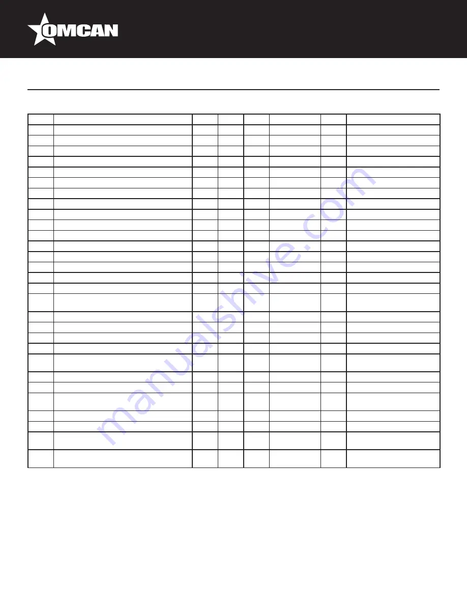
TABLE OF CONTROLLER PARAMETERS

Par.

Description

Type

Min

Max

UOM.

Def.

Parameter visible in models

PS

Password.

F

0

200

-

22

M/S (with 1 & 2 probes), X, Y, C

/2

Probe measurement stability.

C

1

15

-

4

M/S (with 1 & 2 probes), X, Y, C

/4

Select probe displayed.

F

1

3

-

1

M/S (with 2 probes), X, Y, C

/5

Select °C/°F.

C

0 (°C)

1 (°F)

-

0

M/S (with 1 & 2 probes), X, Y, C

/6

Disable decimal point.

C

0

1

-

0

M/S (with 1 & 2 probes), X, Y, C

/7

Enable probe 2 alarm (model M only).

C

0

1

-

0

M

/C1

Probe 1 offset.

F

-50.0

50.0

°C/°F

0

M/S (with 1 & 2 probes), X, Y, C

/C2

Probe 2 offset.

F

-50.0

50.0

°C/°F

0

M/S (with 2 probes), X, Y, C

/C3

Probe 3 offset.

F

-50.0

50.0

°C/°F

0

M/S (with 2 probes), X, Y, C

St

Set point.

S

r1

r2

°C/°F

4

M/S (with 1 & 2 probes), X, Y, C

rd

Control differential.

F

0

19.0

°C/°F

2

S (with 1 & 2 probes), X, Y, C

r1

Minimum set point value.

C

-50

r2

°C/°F

-50

M/S (with 1 & 2 probes), X, Y, C

r2

Maximum set point value.

C

r1

200

°C/°F

90

S (with 1 & 2 probes), X, Y, C

r3

Select direct/reverse operation.

C

0

2

-

0

M/S (with 2 probes), X, Y, C

r4

Night-time set point delta.

C

-50

50

°C/°F

3

S (with 1 & 2 probes), X, Y, C

c0

Compressor and fan start delay on power up.

C

0

100

min

0

S (with 1 & 2 probes), X, Y, C

c1

Minimum time between consecutive compressor 

starts.

C

0

100

min

0

S (with 1 & 2 probes), X, Y, C

c2

Minimum compressor off time.

C

0

100

min

0

S (with 1 & 2 probes), X, Y, C

c3

Minimum compressor on time.

C

0

100

min

0

S (with 1 & 2 probes), X, Y, C

c4

Compressor on time with duty setting.

C

0

100

min

0

S (with 1 & 2 probes), X, Y, C

cc

Continuous cycle duration.

C

0

15

h

4

S (with 1 & 2 probes), X, Y, C

c6

Temperature alarm bypass after continuous 

cycle.

C

0

15

h

2

S (with 1 & 2 probes), X, Y, C

d0

Type of defrost.

C

0

4

-

0

S (with 1 & 2 probes), X, Y, C

dl

Interval between defrosts.

F

0

199

h/min (see dC)

8

S (with 1 & 2 probes), X, Y, C

dt

End defrost temperature set point/defrost tem-

perature threshold with temp. control.

F

-50

130

°C/°F

4

S (with 2 probes), X, Y, C

dP

Maximum defrost duration.

F

1

199

min/s (see dC)

30

S (with 1 & 2 probes), X, Y, C

d4

Defrost when switching the instrument on.

C

0

1

-

0

S (with 1 & 2 probes), X, Y, C

d5

Defrost delay on power-up or when enabled by 

digital input.

C

0

199

min

0

S (with 1 & 2 probes), X, Y, C

d6

Freeze control temperature display during 

defrost.

C

0

1

-

1

S (with 1 & 2 probes), X, Y, C

ALARM SIGNALS

When an alarm is activated, the display shows the corresponding message that flashes alternating with the 

temperature.

•  If fitted and enabled, the buzzer and the alarm relay are also activated. All the alarms have automatic reset 

(that is, they stop when the causes are no longer present), except for alarm ‘CHt’ which has manual reset 

(instrument on/off using the UP button or by disconnecting the power supply).

•  Pressing the SET button mutes the buzzer, while the code displayed, and the alarm relay only go off when 

Summary of Contents for RS-CN-0140-D

Page 1: ...ed 08 20 2020 Toll Free 1 800 465 0234 Fax 905 607 0234 Email service omcan com www omcan com Countertop Refrigerated Showcases Models RS CN 0140 D 0190 D 0240 D Items 44639 44640 46806 Instruction Ma...

Page 2: ...e of Contents Section General Information Safety and Warranty Technical Specifications Installation Operation Maintenance Troubleshooting Parts Breakdown Electrical Schematics Notes Warranty Registrat...

Page 3: ...e It s of the utmost importance to save these instructions for future reference Also save the original box and packaging for shipping the equipment if servicing or returning of the machine is required...

Page 4: ...uina y sta usando ropa apropiada y autorizada Cualquier modificaci n a la m quina an la la garant a y puede causar da os a las personas usando la m quina mientras esta en el funcionamiento REVISE EL P...

Page 5: ...u ft 240 L 7 1 cu ft Power 425 W 451 W 461 W Current 2 64A 2 8A 2 86A Refrigerant R134a Number of Shelves 2 Electrical 110V 60Hz 1 Interior Dimensions 15 8 x 35 5 x 14 5 400 x 902 x 368mm 15 8 x 47 3...

Page 6: ...Increase the distance if the objects surrounding are heating sources When the unit is in place press the brake on the wheels to keep it from moving 5 Fix the shelves on the unit ELECTRICAL CONNECTION...

Page 7: ...et the temperature controller frequently TEMPERATURE CONTROLLER OPERATION Number Function Normal Operation Start Up ON OFF Flash 1 Compressor On Off Call On 2 Fan On Off Call On 3 Defrost On Off Call...

Page 8: ...cycle 2 1 second displays sets the set point For 1 second RESET current EZY set Pressed together 2 and 3 activate parameter reset procedure More than 3 seconds accesses the parameter setting menu pas...

Page 9: ...S with 1 2 probes X Y C c3 Minimum compressor on time C 0 100 min 0 S with 1 2 probes X Y C c4 Compressor on time with duty setting C 0 100 min 0 S with 1 2 probes X Y C cc Continuous cycle duration C...

Page 10: ...tic d6 0 cht Not Active ON Dirty condenser pre alarm Automatic Easy Easy Compact A4 10 Easy Split A4 13 CHt Active ON Dirty condenser alarm Manual Easy Easy Compact A4 10 Easy Split A4 13 EtC Not Acti...

Page 11: ...nsure that refrigeration tubing is not damaged prior to disposal Please discard the unit according to the regulations of local law Troubleshooting Problems Possible Reasons Solutions Remarks No power...

Page 12: ...starts stops frequently The winding of the compressor is short circuit Check with a multi meter replace the compressor Poor contact of the socket Repair or replace The fan of the evaporator does not...

Page 13: ...13 Parts Breakdown Model RS CN 0140 D 44639 Model RS CN 0190 D 44640 Model RS CN 0240 D 46806...

Page 14: ...08 Condenser Fan for CT540AF 12 AA028 Body for CT540AF 21 66967 Thermostat for CT540AF 4 AA009 Condenser for CT540AF 13 AA029 Shelf for CT540AF 22 66968 Switch for CT540AF 5 AA025 Evaporator for CT540...

Page 15: ...15 Electrical Schematics Model RS CN 0140 D 44639 Model RS CN 0190 D 44640 Model RS CN 0240 D 46806...

Page 16: ..._______________ ________________________________________________________________________________________ ________________________________________________________________________________________ ______...

Page 17: ..._______________ ________________________________________________________________________________________ ________________________________________________________________________________________ ______...

Page 18: ..._______________ ________________________________________________________________________________________ ________________________________________________________________________________________ ______...

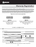
Page 19: ...ter online by visiting OMCAN PRODUCT WARRANTY REGISTRATION 3115 Pepper Mill Court Mississauga Ontario Canada L5L 4X5 https omcan com warranty registration or email to service omcan com Purchaser s Inf...

Page 20: ...relations avec nos clients et les fabricants de valeur Aujourd hui avec des partenaires en Am rique du Nord Europe Asie et Am rique du Sud nous travaillons continuellement am liorer et d velopper l e...

Reviews: