16
Installation
Operation
Omcan coolers with HC refrigerants (R290 / R600) are designed to operate under a specific electric voltage.
Check cooler’s serial label to make sure that the electrical classification is adequate for installation.
IMPORTANT: ground connection is a protection system for equipment connected to electrical network.
It is used in electrical installations to avoid current pass-through to user due to an isolation failure of
active conductors.
•
This cooler must be connected to physical ground. In case a short circuit occurs, ground connection
reduces the risk of electrical shock.
• Cooler is equipped with a power cord with a ground cable with a physical ground connection plug. Plug
must be connected to an adequately-installed outlet and ground connected; if you don’t have this type of
plug, it is your responsibility and obligation to have it installed.
• Please contact a certified electrician or a certified technician if you have questions about ground
connections.
•
Never use extension cords, as that action will void the warranty.
• Under no circumstances cut off or remove the third ground connection pin from power cord. Do not use an
adapter; if this recommendation is not followed, it may cause burns or death to user due to electrical shock.
• For optimal operation, it is recommended to have this equipment connected to a dedicated circuit outlet
that is for cooler use only.
• Connect plug firmly to electrical outlet making sure it is inserted all the way in.
POWER CORD
Cooler is equipped with a polarized power cord, with ground connection. Do not attempt to eliminate ground
connection or use two-terminal adapters.
AVOID RISKS: if the power cord or other electronic components are damaged, only the manufacturer
or authorized technician may repair them to avoid danger.
TURNING ON THE COOLER
After having transported and installed the cooler, let it stand for at least twelve hours to allow
compressor oil to fully settle.
Once the installing instructions have been followed, connect the cooler per electrical specifications indicated on
serial number label (placed inside cabinet). For your own safety, avoid touching the device with wet hands or
damp or feet. You should not handle cooler when barefoot.
Summary of Contents for VRD26
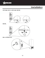
Page 13: ...13 Installation LEVELING SKID LEVELING SCREW WHEEL WALL SEPARATOR...
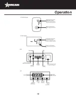
Page 19: ...19 Operation...
Page 27: ...27 Parts Breakdown Model VR08 41215 General Assembly...
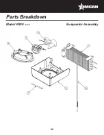
Page 28: ...28 Parts Breakdown Model VR08 41215 Evaporator Assembly...
Page 29: ...29 Parts Breakdown Model VR08 41215 Condenser Assembly...
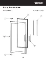
Page 30: ...30 Parts Breakdown Model VR08 41215 Door Assembly...
Page 32: ...32 Parts Breakdown Model VR06 41214 General Assembly...
Page 33: ...33 Parts Breakdown Model VR06 41214 Evaporator Assembly...
Page 34: ...34 Parts Breakdown Model VR06 41214 Condenser Assembly...
Page 35: ...35 Parts Breakdown Model VR06 41214 Door Assembly...
Page 37: ...37 Parts Breakdown Model VR12 41217 General Assembly...
Page 38: ...38 Parts Breakdown Model VR12 41217 Evaporator Assembly...
Page 39: ...39 Parts Breakdown Model VR12 41217 Condenser Assembly...
Page 40: ...40 Parts Breakdown Model VR12 41217 Door Assembly...
Page 42: ...42 Parts Breakdown Model VR10 41216 General Assembly...
Page 43: ...43 Parts Breakdown Model VR10 41216 Evaporator Assembly...
Page 44: ...44 Parts Breakdown Model VR10 41216 Condenser Assembly...
Page 45: ...45 Parts Breakdown Model VR10 41216 Door Assembly...
Page 47: ...47 Parts Breakdown Model G319 HC 45445 Model G319 41161 General Assembly...
Page 48: ...48 Parts Breakdown Model G319 HC 45445 Model G319 41161 Evaporator Assembly...
Page 49: ...49 Parts Breakdown Model G319 HC 45445 Model G319 41161 Condenser Assembly...
Page 50: ...50 Parts Breakdown Model G319 HC 45445 Model G319 41161 Door Assembly...
Page 53: ...53 Parts Breakdown Model VRD26 41219 General Assembly...
Page 54: ...54 Parts Breakdown Model VRD26 41219 Evaporator Assembly...
Page 55: ...55 Parts Breakdown Model VRD26 41219 Condenser Assembly...
Page 56: ...56 Parts Breakdown Model VRD26 41219 Door Assembly...
Page 58: ...58 Parts Breakdown Model VRD37 42862 General Assembly...
Page 59: ...59 Parts Breakdown Model VRD37 42862 Evaporator Assembly...
Page 60: ...60 Parts Breakdown Model VRD37 42862 Condenser Assembly...
Page 61: ...61 Parts Breakdown Model VRD37 42862 Door Assembly...
Page 63: ...63 Parts Breakdown Model VRD37 HC BW 45249 General Assembly...
Page 64: ...64 Parts Breakdown Model VRD37 HC BW 45249 Evaporator Unit...
Page 65: ...65 Parts Breakdown Model VRD37 HC BW 45249 Condenser Unit...
Page 66: ...66 Parts Breakdown Model VRD37 HC BW 45249 Door Assembly...
Page 68: ...68 Parts Breakdown Model VRD43 41218 General Assembly...
Page 69: ...69 Parts Breakdown Model VRD43 41218 Evaporator Assembly...
Page 70: ...70 Parts Breakdown Model VRD43 41218 Condenser Assembly...
Page 71: ...71 Parts Breakdown Model VRD43 41218 Door Assembly...
Page 73: ...73 Parts Breakdown Model G372 41220 Model G372 BLACK 45250 General Assembly...
Page 74: ...74 Parts Breakdown Model G372 41220 Model G372 BLACK 45250 Evaporator Assembly...
Page 75: ...75 Parts Breakdown Model G372 41220 Model G372 BLACK 45250 Condenser Assembly...
Page 76: ...76 Parts Breakdown Model G372 41220 Model G372 BLACK 45250 Door Assembly...
Page 78: ...78 Parts Breakdown Model VR1 5 45800 General Assembly...
Page 79: ...79 Parts Breakdown Model VR1 5 45800 Condenser Assembly...
Page 80: ...80 Parts Breakdown Model VR1 5 45800 Door Assembly...
Page 82: ...82 Parts Breakdown Model VR04 45801 General Assembly...
Page 83: ...83 Parts Breakdown Model VR04 45801 Condenser Assembly...
Page 84: ...84 Parts Breakdown Model VR04 45801 Door Assembly...
Page 86: ...86 Parts Breakdown Model VFS24 41221 General Assembly...
Page 87: ...87 Parts Breakdown Model VFS24 41221 Evaporator Assembly...
Page 88: ...88 Parts Breakdown Model VFS24 41221 Condenser Assembly...
Page 89: ...89 Parts Breakdown Model VFS24 41221 Door Assembly...
Page 91: ...91 Electrical Schematics Model VR08 41215...
Page 92: ...92 Electrical Schematics Model VR06 41214...
Page 93: ...93 Electrical Schematics Model VR12 41217...
Page 94: ...94 Electrical Schematics Model VR10 41216...
Page 95: ...95 Electrical Schematics Model G319 HC 45445 Model G319 41161...
Page 96: ...96 Electrical Schematics Model VRD26 41219...
Page 97: ...97 Electrical Schematics Model VRD37 42862...
Page 98: ...98 Electrical Schematics Model VRD37 HC BW 45249...
Page 99: ...99 Electrical Schematics Model VRD43 41218...
Page 100: ...100 Electrical Schematics Model G372 41220 Model G372 BLACK 45250...
Page 101: ...101 Electrical Schematics Model VR1 5 45800...
Page 102: ...102 Electrical Schematics Model VR04 45801...


