background image


Version 1.2 - October 08 


28923 

Page 20


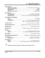
9. Specifications 

ANALOG INPUTS 
 

Basic accuracy (5-45°C): 

..............................................± (0.05% re 0.025% range) 


Common mode rejection: 

...........................................................................................100dB 


Input impedance: 

...................................................................................................> 1MOHM 


Linearity: 

..................................................................................................................0.0015% 


Series mode line rejection:

...........................................................................50/60Hz 100dB 


DIGITAL INPUTS  
 

Zero input voltage

....................................................................... 0 to 0.5V (or shorted input) 


One input voltage

..................................................................2.7 to 5V (or open circuit input) 


Input protection

......................................will turn on below about -0.5V and above about 6V 


ANALOG-DIGITAL CONVERSION 
 

Type: 

....................................................................................................................Sigma-Delta 


Resolution: 

.....................................................................................................................24bit 


Sampling rate: 

..................................................................Up to 20/100 readings per second 


Note: 

100Hz Mode not available on 1F8 models  


ALARM OUTPUTS

.......................................................................4 x open drain FET (18V 0.1A Max) 


SENSOR POWER SUPPLY

..............................Regulated 5 VDC (50mA) or supply voltage (100mA) 


TIME AND DATE

...........................................................................................In built clock in 3 formats 


SCALING DATA

.......................................................Displays readings in preferred engineering units 


MEMORY


Internal: 

...............................................................................16Mb (Up to 1,800,000 readings) 


External:

.......................................................


Up to 256Mb removable MMC/SD memory card 


RESOLUTION

.................................................................................................Up to 6 significant digits 


PROGRAMMING/LOGGER SET-UP

..................... ..........OMEGALOG

®

 or OMEGALOG

®

 Plus software 


COMMUNICATION

.......................................................................................USB 1.1 and 2.0 / RS232 


External options

: .......................................................................GSM, Ethernet and wireless 


POWER SUPPLY 


Internal

:............................................................................................6*x AA Alkaline batteries 


External

: ..........................................10-18VDC Reverse polarity and over-voltage protected 


* Maximum operating temperature for supplied alkaline batteries is 50°C 

Summary of Contents for OM-SQ2020 Series

Page 1: ......

Page 2: ......

Page 3: ...ith your Logger 5 4 Quick Start Example 8 5 Download Process Explained 12 6 Menu and Navigation 13 7 Connections 15 8 Accessories 17 9 Specifications 19 After reading this guide please re fer to the H...

Page 4: ...USB CABLE E Mounting bracket stand for logger F Batteries 6 x AA G Current shunt resistors for 4 to 20mA inputs 10R x 4 OM SQ CS H Connectors 6 way x 4 OM SQ TB6 4 way OM SQ TB4 3 way OM SQ TB3 with...

Page 5: ...ent batteries are of the same manufacturer type and condition 2 1 Installing the batteries 2 2 Power indicator Battery indicator When logging please ensure that the batteries in the unit have sufficie...

Page 6: ...nsure you have administration rights on the PC you wish to install software on 2 Ensure any current OMEGA applications are closed 3 Insert the CD into the CD DVD drive of your computer and wait for it...

Page 7: ...locate the driver On the Found New Hardware Wizard select No not this time and for all the other screens select Next to complete the installation On detection of the logger the PC will launch the driv...

Page 8: ...are ready to communicate to your logger If you experience any problems refer to Troubleshooting 20XX USB Drivers in OMEGA LOG help Ethernet Before using the Ethernet connection please read the configu...

Page 9: ...sure the correct logger Type and communication method is selected Logger type can be viewed from the OMEGALOG Assistant if you need to make any changes select Logger Selection from the toolbar or run...

Page 10: ...scroll down the Sensor Type column to Ref Junction 1 This is the input you will be reading in this example The Job Description can be used to describe your setup In the OMEGALOG Assistant click Logger...

Page 11: ...logger and start logging Let the unit log for a few minutes Click on Logger Control icon to pause or stop the logging process In the Logger Control window you can view relevant information on the stat...

Page 12: ...ile name is shown on the right this shows the date and start time In this example you will download and view the Data in the Analysis window Start by selecting the Data File and Graph Data action then...

Page 13: ...can be viewed it must be converted by OMEGALOG for Analysis or exported to csv or xls format depending on the PC software being used The conversion process can be performed in one of three ways within...

Page 14: ...etail To use the OM SQ2020 2040 control panel press the opening display will be shown see right The display timeout is preset to 10 seconds however this can be changed by selecting the Configuration t...

Page 15: ...hrough the channels 6 3 3 Status The Status menu gives you access to information relating to the logger such as memory and power supply voltage You can also override the alarm outputs in here 6 3 4 Se...

Page 16: ...ALOG during the setup Follow the wiring diagram to attach the required sensor If you would like to print the diagrams in more detail or view at a later stage select File Print from Logger Setup The ex...

Page 17: ...t State Input 8 9 Ground 10 Alarm Output A 11 Alarm Output B 12 Alarm Output C 13 Alarm Output D 14 Auxiliary Output ve 15 Auxiliary Output ve 16 Auxiliary Output ve 17 Auxiliary Output ve 18 Ground 1...

Page 18: ...ngineering Ethernet Wireless GSM RS232 to Ethernet Converter consisting of adaptor box and modem setup Cable Ethernet configuration software is suitable for Windows 2000 and XP only GSM Modem kit comp...

Page 19: ...ertificates are traceable to National Standards OM SQ2010 OM SQ2020 CAL OM SQ2040 OM SQ2040 CAL Power supplies 100 240V AC 50 60Hz supplied with 3 single fit mains plugs for UK Euro and US OM SQ UNIV...

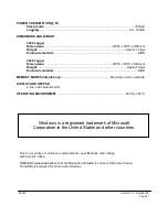
Page 20: ...te 100Hz Mode not available on 1F8 models ALARM OUTPUTS 4 x open drain FET 18V 0 1A Max SENSOR POWER SUPPLY Regulated 5 VDC 50mA or supply voltage 100mA TIME AND DATE In built clock in 3 formats SCALI...

Page 21: ...aterial ABS MEMORY MODES internal only Stop when full or overwrite DISPLAY AND KEYPAD 2 line x 20 character LCD OPERATING ENVIRONMENT 30 C to 65 C Windows is a registered trademark of Microsoft Corpor...

Page 22: ...Version 1 2 October 08 28923 Page 22 Personal Notes...

Page 23: ......

Page 24: ......

Reviews: