Hardware
7-3
Ethernet Interface, section of Rear Panel
LED Indicators
Activity - ON when data is being sent or received through the internet.
Link - ON when the NetScan unit has a solid connection to the internet.
Ethernet - ON when the ethernet interface is enabled and functioning properly.
OFF when the ethernet interface is disabled.
FLASHES when a problem exists that requires factory attention.
Ethernet Connector
Accepts a 10Base-T type ethernet cable for connecting to a PC ethernet connector, or to an
ethernet hub.
Configuration (DB9)
Accepts a DB9 cable for communicating with an available PC COMM port. This connector is
only needed during the configuration of address settings for ethernet operation. See
Chapter 2 for more detailed information.
Ethernet or
RS-232/422 Selector
Two-position switch used to the select ethernet or serial (RS-232/422) mode of operation.
Power Aspects
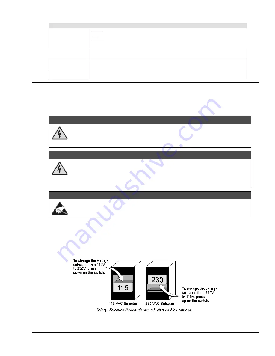
Changing the Voltage Setting
Based on your order, your NetScan system was set at the voltage indicated by a sticker or tag (located on the rear of
the unit, near the power switch). If you need to change the voltage selection, complete the following steps.
:$51,1*
Never disassemble NetScan’s case while it is connected to the AC power line! Internal
voltage potentials exist which could cause bodily injury or death!
Prior to disassembly: (1) turn off power, (2) disconnect analog lines, (3) disconnect AC
power line, then disconnect any other cables.
:$51,1*
Never disconnect the AC power line from NetScan while analog connections to an external
device exist! Common mode voltage potentials exceeding 60 VDC or 30 Vrms may exist
which could cause bodily injury or death!
Prior to disassembly: (1) turn off power, (2) disconnect analog lines, (3) disconnect AC
power line, then disconnect any other cables.
&$87,21
Use approved ESD precautions, including static-free work area and grounded wrist strap,
when handling circuit boards and electronic components. Failure to do so could cause
equipment damage due to electrostatic discharge.
1.
Ensure the NetScan is not connected to any power source.
2.
Remove two upper side screws (near front of unit, and on side of unit) and slide top cover plate free of
NetScan unit.
3.
Locate the two-position slide on the power supply board. You will notice the switch above the AC
power inlet. The number visible (115 or 230) indicates the selected power setting.
Summary of Contents for OMB-NETSCAN 1500
Page 6: ...iv NetScan User s Manual...
Page 18: ...1 12 Configuring and Starting NetScan NetScan User s Manual Notes...
Page 38: ...3 8 General Information and Specifications NetScan User s Manual Notes...
Page 82: ...4 44 ChartView Software Reference NetScan User s Manual Notes...
Page 118: ...6 20 Calibration NetScan User s Manual...
Page 140: ...A ii NetScan User s Manual...
Page 192: ...API Command Reference Appendix A A 52 NetScan User s Manual Notes...
Page 237: ...Appendix D Registers Data Formats Queries NetScan User s Manual D 13...
Page 244: ...NetScan Program Examples Appendix E E 2 NetScan User s Manual...
Page 248: ...ASCII Code Summary Appendix F F 4 NetScan User s Manual Notes...
Page 250: ...NetScan Error Messages Appendix G G 2 NetScan User s Manual Notes...
Page 252: ...Abbreviations Appendix H H 2 NetScan User s Manual Notes...
Page 254: ...NetScan User s Manual...


