4-36 ChartView Software Reference
NetScan User’s Manual
Note: When using a channel as a reference channel, remember that lower numbered channels are calculated
ahead of higher numbered channels, e.g., CH1 is calculated ahead of CH2. This makes a difference
when subtracting a reference channel in regard to the time aspect of the reference value.
If the channel is configured for Volts, the units automatically change to V; at this point, you have the
option of selecting the millivolt unit (mV). The user can also change each channel to apply a linear
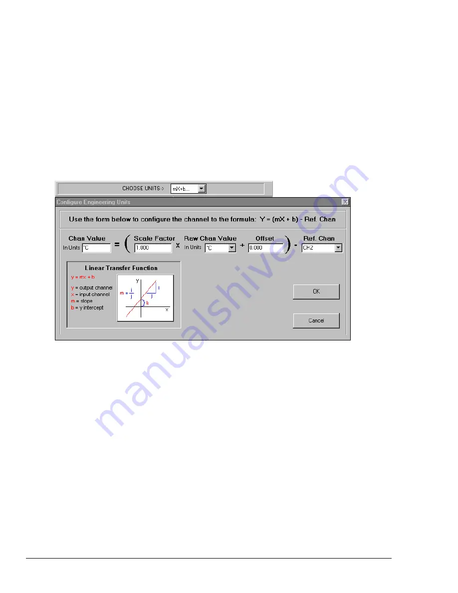
equation (mX+b) to the data. When the mX+b option is selected the Configure Engineering Units dialog
box is displayed. You are prompted to define “m” and “b” and the engineering units label; as well as which
standard units the mX+b equation should be applied to. The engineering units chosen will be displayed in
the “Units” column, and the “mX+b” equation will be applied to the reading from the device before the
reading is displayed or written to disk.
The mX+b option is convenient for obtaining a value that has a linear relation to a channel reading.
X is the scanned voltage value read back from the acquisition device
m is [but not limited to] a proportionality constant or gain factor, but not zero.
b is the offset value (the value of the calculated reading when the scanned value is “zero”).
Alarm Configuration Columns
1)
Low Limit
Set alarm low limit.
2)
High Limit
Set alarm high limit.
3)
Hysteresis
A hysteresis value can be set for each channel to avoid a “chatter” problem.
See Appendix C, Set Point Hysteresis, page C-27.
4)
Alarm #
You can assign one alarm number (1 to 32) to a channel. Any number of channels can be
assigned to the same alarm number. A given digital output will be set “true” (1) if at least one of the
common channels (assigned to a single alarm) enters an alarm state.
Acquisition Setup Dialog Box
The information entered in the Acquisition Setup dialog box is used by the Arm Acquisition command
to set up the acquisition of data to disk. When the trigger is satisfied, the scans are collected at the
selected scan frequency and stored to disk in the designated file.
The Acquisition Setup dialog box can be accessed in one of three ways: a) clicking on the Channel
Configuration button (item 8 in Main Window figure), b) clicking on the Acquisition Setup tab from
the Channels or Data Destination dialog boxes, c) using the Setup pull-down menu and selecting
Acquisition.
ChartScan, NetScan, and MultiScan have two modes of data acquisition, these are:
•
Normal mode
•
High-speed, single-channel mode (burst mode)
Summary of Contents for OMB-NETSCAN 1500
Page 6: ...iv NetScan User s Manual...
Page 18: ...1 12 Configuring and Starting NetScan NetScan User s Manual Notes...
Page 38: ...3 8 General Information and Specifications NetScan User s Manual Notes...
Page 82: ...4 44 ChartView Software Reference NetScan User s Manual Notes...
Page 118: ...6 20 Calibration NetScan User s Manual...
Page 140: ...A ii NetScan User s Manual...
Page 192: ...API Command Reference Appendix A A 52 NetScan User s Manual Notes...
Page 237: ...Appendix D Registers Data Formats Queries NetScan User s Manual D 13...
Page 244: ...NetScan Program Examples Appendix E E 2 NetScan User s Manual...
Page 248: ...ASCII Code Summary Appendix F F 4 NetScan User s Manual Notes...
Page 250: ...NetScan Error Messages Appendix G G 2 NetScan User s Manual Notes...
Page 252: ...Abbreviations Appendix H H 2 NetScan User s Manual Notes...
Page 254: ...NetScan User s Manual...


