4.2.4 Common Mode Voltage < +/-10V / Differential Inputs
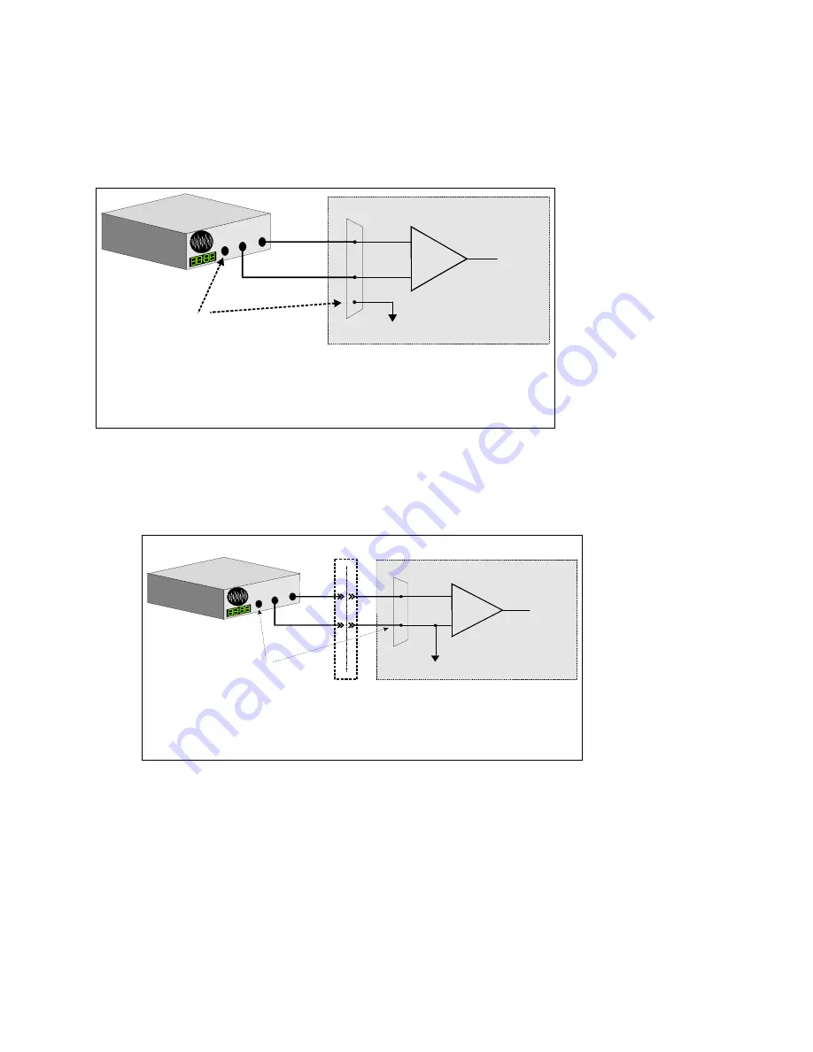
Systems with varying ground potentials should always be monitored in the differential mode. Care is required to assure that
the sum of the input signal and the ground differential (referred to as the common mode voltage) does not exceed the
common mode range of the A/D board (+/-10V on the PCI-DAS1000). The diagram below show recommended connections
in this configuration.
4.2.5 Common Mode Voltage > +/-10V
The PCI-DAS1000 will not directly monitor signals with common mode voltages greater than +/-10V. You will either need
to alter the system ground configuration to reduce the overall common mode voltage, or add isolated signal conditioning
between the source and your board.
11
+
-
In p u t
A m p
To A /D
A /D B o a rd
I/O
C o n n e c to r
LL G N D
C H H igh
C H L ow
S ig n a
l S ou
rce
w it
h C o m
m on
M o d
e Vo l
tage
S ign a l so urce a n d A /D b o a rd
w ith c o m m on m o d e vo lta g e
con n ecte d to a d iffe ren tia l in p u t.
G N D
T he vo lta g e differen tia l
b etw een the se g ro un d s,
a dde d to the m ax im u m
in pu t sig na l m ust sta y
w ith in + /-10 V
S ystem w ith a Large C om m on M ode Voltage ,
C onne cte d to a S ingle-E nded In put
I/O
C o n n e c to r
+
-
In p u t
A m p
To A /D
LL G N D
C H IN
A /D B o a rd
L
arge c
om m
on
m
od e v
olta g
e
bet
w een
s ig nal
sou
rc e &
A /D
b oar
d
G N D
Is o la tio n
B a rrie r
W h en the voltage d ifferenc e
be tw ee n sig n a l sou rc e a nd
A /D boa rd g ro un d is large
en o ug h so the A /D boa rd ’s
co m m o n m od e ra n ge is
ex ceed e d, iso la te d sig nal
co ndition ing m ust b e add ed.


